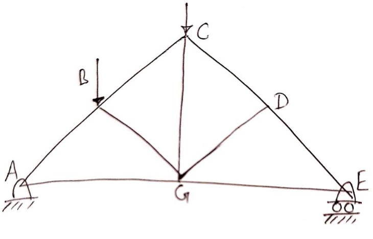
Identify the zero-force members present when the trusses shown in the following problems are subjected to the load- ings indicater B H G F
Identify the zero-force members present when the trusses shown in the following problems are subjected to the load- ings indicater B H G F

International Edition---engineering Mechanics: Statics, 4th Edition
4th Edition
ISBN:9781305501607
Author:Andrew Pytel And Jaan Kiusalaas
Publisher:Andrew Pytel And Jaan Kiusalaas
Chapter10: Virtual Work And Potential Energy
Section: Chapter Questions
Problem 10.7P: The linkage is made of two homogenous bars of weights shown in the figure. Determine the horizontal...

Related questions
Question
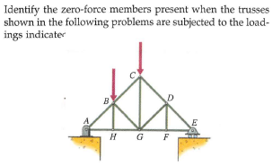
Transcribed Image Text:Identify the zero-force members present when the trusses
shown in the following problems are subjected to the load-
ings indicater
B
H G F
Expert Solution
Step 1
In given truss, two members DF and BH are directly attached with members GE and AG respectively without any external force so members DF and BH will be zero-force members. On removing members DF and BH from the given truss, a new truss is given as,

Step by step
Solved in 2 steps with 1 images

Recommended textbooks for you
International Edition---engineering Mechanics: St…
Mechanical Engineering
ISBN:
9781305501607
Author:
Andrew Pytel And Jaan Kiusalaas
Publisher:
CENGAGE L
International Edition---engineering Mechanics: St…
Mechanical Engineering
ISBN:
9781305501607
Author:
Andrew Pytel And Jaan Kiusalaas
Publisher:
CENGAGE L