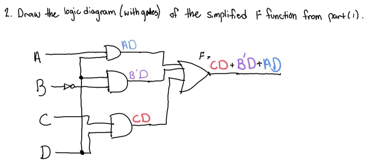
Implement the logic diagram from part (2) with only NAND gates.


Q: Using the techniques for combining sources and combining resistors, calculate the voltage Vx across…
A: In series, resistors are connected end-to-end, forming a single path for current to flow through.…
Q: In the circuit shown, Ics = 0.5fA, VB = 4V, V₁ = ∞, and ß = 100. Find all the node VA voltages and…
A: The question is about finding all node voltages and branch currents.
Q: For a ortain dynamometer ammeter, mutual industries 'M' varies with deflection '0' as M = -15 cos (0…
A: Here,the mutual inductance varies with deflection as, a direct current, deflection angle,
Q: DG CIRCUIT CHALLENGE SOLVING FOR DC CIRCUIT COMPONENT VALUES
A: In the given questions we need to calculate the voltage current and power of each element.
Q: Using nodal analysis, show that VO is equal to 2.12∠(75°)V for the circuit given.
A: In this question, we need to determine the voltage Vo as shown the circuit using the nodal…
Q: Show that I1=0.7781∠(-161.9°)A using superposition.
A: In the given figure below, we need to calculate the current I1 using superposition theorem.…
Q: Consider the following schematics. (1) What is the dynamic order of this network? Explain your…
A: In this question, we need to determine the dynamic order of the network and transfer function of the…
Q: Although, geometrically no difference exists between the source and a drain of a MOSFET, drain and…
A: The above question is based on the physical structure of NMOS.
Q: 2.8. In the system shown in Figure P2.8, find I, I, and I, if (a) Z₁ = Z = j1.0, Z = 10.9 (b) Z₁ =…
A: The given circuit diagram is shown below,
Q: a. Simplify the block diagrams of the system shown in figure 4 into a single block. G₁ E₁ E₂ G₁ H₁…
A: Block reduction techniques in engineering, specifically in the context of control systems, deal with…
Q: Find the Norton Equivalent with respect to Terminals A and B for: +280 V R1 2 ΚΩ R2 2 ΚΩ 0.2 *i_1 R3…
A: Norton's Theorem states that any linear electrical network, consisting of voltage and current…
Q: 1. If an amplifier has 6 dB of gain, how much is the power increased? How much is the voltage…
A:
Q: I i(t) 0 t1 t2 Given: I= 270A, tl= 26ms, t2= 69ms, t3= 380ms, L= 260mH i(t) (1) t3 v(t)
A: Given:Waveform of current through an inductor is,withwe need to find:Inductor voltage at 380 ms.
Q: An electric heater is designed to operate at 660W from a 120V source. If the source voltage drops to…
A: Power consumed P = 660 W.Initial voltage V = 120 V.Final voltage V = 80 V.
Q: On a 20 second exposure, a star with magnitude B = 15 produces an SNR = 100 signal with a small…
A: A condition in which photon noise predominates as a source of noise in an optical system is referred…
Q: Q5. Consider the linear circuit below. Given that (i) I₁ = 4 A when V₁ = −3 V and (ii) I₁ = -2 A…
A: We need to find out current and voltage for the given circuit.
Q: AC3 For the following sine waveform, if E = 7 V, what is the voltage at t = 2ms? (write your answer…
A: In this question, we need to determine the voltage at t= 2 ms. If E = 7 V
Q: Sketch the output waveform from the RC low-pass filter for (a) RC= 1 us, (b) RC= 100 s. n 10μs 10μs…
A: GivenThe RC filter circuit is given by,The input waveform is,To findDraw the output waveform for,(a)…
Q: find Closed-loop transfer function, Root Locus, Step Response ,Bode Plot , Nyquist plot and lead…
A: Since you have posted a question with multiple sub parts, we will provide the solution only to the…
Q: 8.10 Calculate Z₁ for maximum average power transfer in the circuit, and find the average power…
A: In this question, we need to determine the load impedance for maximum power transfer to load and…
Q: 4.38 Solve the problems in Example 4.2 using the constant- voltage-drop (V₂ = 0.7 V) diode model.…
A: Given circuit: Voltage drop in the diodes VD = 0.7 voltsAsked to find the values of I and V?
Q: 40. Sketch the waveform for i of the network of Fig. 1.66 ift, 2r, and the total reverse recovery…
A: The diode circuit with volt-time waveform,total reverse recovery time,
Q: Consider a bipartite network, with its two types of nodes, and suppose that there are n1 nodes of…
A: For a bipartite network, with its two types of nodes, such that there are n1 nodes of type 1 and n2…
Q: Show that the average power absorbed by each resistor is P2Ω.=P4Ω.=7.20W.
A: In this question, we need to determine the average power absorbed by each resistance as shown the…
Q: Problem 5-3. For the circuit of figure P5-3, find the Thevenin equivalent with respect to the…
A: The given circuit isWe need to find the Thevenin's equivalent circuit at the terminals a-b.
Q: Show that V0=2.98∠(-153.43°) V
A:
Q: 1-14 How many independent equations can be obtained from the following circuit with Kirchhoff's…
A:
Q: 1. 2. Determine the frequency at which a 1 mF capacitor and a 10 mH inductor will have the same…
A: In this question, we need to determine the frequency in the first question and value of inductance…
Q: by The electric field of a wave propagating through a certain nonmagnetic material is given 0 ·…
A:
Q: 2. Solve for 12 005 200€ v + √x (t). 100MF 201 ↑ 3A7 15H 10.2 Ux
A: The given circuit isWe need to find the voltage vx.
Q: -3 Consider a gallium arsenide pn junction at T = 300 K with doping concentrations of Na = 5 X 10¹5…
A: The doping concentrations,The temprature,
Q: You have a 3 phase delta connected resistor network. The Line voltage is 240V and the line current…
A:
Q: An inductor can store an energy 0.4 J. The current carried by the wire is 10A. What is its…
A: Energy is given as, current is given as, I = 10 A.
Q: According to the following figure, the LED of a 7-segment decoder (Inset) will display a "0" when…
A: Given:a circuit, To find:For what sequence of VI1, VI2, . . . . , VI7 the seven segment LED will…
Q: Question 5: Calculate: a) the value of a single resistor to replace all resistors b) all currents…
A: Given circuit:Asked to find thesingle value of all the resistorsif all resistances are in kilo ohms…
Q: If the relamping costs $8 per lamp (price of a lamp), and the cost is $2 for each fixture, estimate…
A: Lamp cost per peice = $8Cost per fixture = $2The lamp specifications are 2x22W, T-5, fluorescent,…
Q: 1. Why does transmission of a 2-kHz square wave require greater bandwidth than transmission of a…
A: The bandwidth required for the transmission of a signal is determined by the frequency content and…
Q: the circuit shown in (Figure 1). Suppose that R = 12. Figure 12 02 www 240 V 1 t=0 R 402 www 72 mH…
A: Given Data:A DC resistive circuit with,Input voltage To Find:The percentage of the initial energy…
Q: 5-3-22 Find 1, in the network in Eig.P5.3.22 using Thévenin's theorem. τον 1 ΚΩ ww 12 mA ΣΖΚΩ ΣΚΟΥ…
A: The question is about finding the current I0 using thevenin's theorem.
Q: Find the Thevenin’s equivalent circuit from input of node a and b in Figure below
A: The given circuit isWe need to find the Thevenin’s equivalent circuit at the terminals a-b.
Q: Question 01 A. what is Ir in milliamperes if RL = 180 ohms B. In Figure 3, what is iL, in…
A: Calculate IR in milliamperes if RL = 180 ohms B. In figure, what is IL, in milliamperes if RL = 180…
Q: I = 4/45° A 1 2 Ω VI, + -j4 Ω V
A: The circuit diagram,
Q: You count 8 cycles across 8.3 time divisions on an oscilloscope screen. The time sweep is set to…
A: Number of cycles, The time of each division is 2.5 ms,The peak voltage,
Q: determine the period, frequency, average value, and rms value. |||||||||||| Vertical sensitivity =…
A: The waveform,Verticle sensitivity, 20mV/divHorizontle senstivity,
Q: 1. A frequency modulated wave has an angular carrier frequency wc = 8000 rad/sec and a modulation…
A: Given carrier frequency= 8000rad/sec Modulation index = 10 Modulation signal m(t) = 20cos(5t) Find…
Q: Let G(s)-7.6s. Obtain the over-all transfer function, then substitute s=1. Give the calculated value…
A: Given: obtain the overall transfer function then substitude s=1.Answer the value in 3 decimal…
Q: Question 4: Potential divider circuit illustrated below. R₁ VA (i) (ii) (iii) R₂ VB J RL a) Show…
A: Given circuit:
Q: In the following circuit VBB = 0.2 V, and I1=2.4 mA. Assume 3 =54, and VBE = 0.7V Find the maximum…
A: In this question, we need to determine the maximum resistance R3 while keeping the transitor in…
Q: Q-1) هد Please write the magnetic circuit And explain the steps.
A: Given figure:Asked to explain the ircuit and write magnetic circuit?
Q: Write the MATLAB commands to reduce the block diagrams below: 1. R(s) 5 115 2 2.s C(s)
A: The given block diagram is We need to find the transfer function using MATLAB.
Implement the logic diagram from part (2) with only NAND gates.

Step by step
Solved in 3 steps with 2 images


- Realize the following function ; " on the image " using a(a) 4-to-1 multiplexer, and draw the logic diagram.(b) 8-to-1 multiplexer, and draw the logic diagram.You may use external gates if needed.Solve the following in Boolean Algebra: (BC'+A'D)(AB'+CD') A. Simplify the given function using Boolean simplification. B. Draw the logic diagram of the given equation. C. Draw the logic diagram of the simplified equation. D. Give the number of of logic gates used in the given design E. Give the number of logic gates used in the simplified design.Given the following logic function: F = x’y’z’ + xyz + xy’z + x’yz’ Draw the logic diagram after simplification. Verify the logic using Logisim.
- Prove the equality of the following boolean expression (AB)'.(CD)'=(AB+CD)'.state this theorem.implement using logic gates alsoPLSS ANSWER IN 10MINS Draw the complete logic diagram from the given logic equation, maximum of 2 inputs per gates used. Label the inputs and output properly.F = X'YZ+XY"Z(+)(XZ')'Implement the following logic function using only 3-8 decoders and logic gates. f(a,b,c,d ) Σ m(2,4,6,8,10,14,15)
- Design a circuit with logic gates that tell us if a number less than 10, codedin binary, it is either prime (1) or not (0). Minimum up to 16 combinations.True tableII. Boolean functionIII. Simplification procedure by any of the methodsSimplify the given circuit to a minimum number of logic gates. Show truth table, simplification solution and simplified circuit diagrama) Write the output expression of the logic circuit shown in the figure. b) Minimize the expression using Boolean laws and theorems. c) Implement the minimized expression using 2 input NOR gates only.
- Draw logic diagrams (network of gates) of the circuits that implement the original and simplifiedexpressions of the following:a’bc + abc’ + abc + a’bc’Using Table 16.1 , identify the components of the logic system shown in the figure.What is the correct input combination for the given logic circuit below if the output is F = 1? a. 1, 1, 1 b. 0, 0, 1 c. 0, 1, 0 d. 1, 0, 0