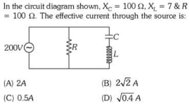
In the circuit diagram shown, X=100 2, X₁ = 7 & R =100 2. The effective current through the source is: 200V eeeeee (A) 2A (C) 0.5A (B) 2√2 A (D) √0.4 A


Q: Required information A 110-V rms, 60-Hz source is applied to a load impedance Z. The apparent power…
A: RMS (Root Mean Square) current is a measure of the effective or equivalent continuous current that…
Q: A)What is the indication of the wattmeter of the figure? B) Draw the new circuit by relocating to…
A: The given circuit is shown below.
Q: In the DeviceNet network below, what is the address of a barcode scanner connected to Port 5 of the…
A: The given image is shown below.
Q: Derive the Transfer Function of the following RC and RLC circuits: (Hint: Solve directly in the…
A: Given:a circuit,we need to derive transfer function assuming zero initial conditions.
Q: Q1\Calculate the total DC resistance of a 100 meter roll of 2.5mm² copper wire if the resistivity of…
A: According to the question, we need to calculate the total DC resistance of a 100 m roll of 25 mm2…
Q: Find the maximum power that can be delivered to the resistor R in the circuit in Fig. below. Enter…
A: In the given question we need to calculate the maximum power transfer to load.
Q: 4. Calculate position of Fermi level with respect to the conduction band in intrinsic silicon at…
A: Position of Fermi Level with Respect to the Conduction Band in Intrinsic Silicon at Room…
Q: a 240 v, 50Hz supply. Q.7) The circuit shown in figure 4 is connected to Determine the current…
A: Determine the current waveform, the mean load voltage and the mean load currents
Q: Needs Complete typed solution with 100 % accuracy.
A: The objective of this question is to determine the readings on an ideal ammeter and voltmeter in a…
Q: 8. In the circuit below, determine the node voltage Vд using node voltage analysis. The 60 V…
A:
Q: Example: consider the open-loop T.F GH(S)=1/S(S+2). Design PD- controller such that time constant…
A: The OLTF,
Q: please help with 5 and 6 thank you i will like
A: #5 Current, IC=1.9714mA#5 Voltage, VCE=10.1144V#6 Current, IC=29.0476μA#6 Voltage,…
Q: Consider the circuit shown on the figure below (Figure 1). Suppose that Ri 12 11. Ry 2811, Rs 11 12…
A: The given circuit is drawn below:
Q: 3.2
A: Detailed solution of the problem is attached below,Feel free to comment if you want any further…
Q: V 2 R2 R₁ 0 ww 3 ala Ia Ra 7 6 A B 5 Determine the voltage drop (in volts) from A to B for the…
A: The circuit diagram,
Q: 2. An 12 volt battery is connected to a configuration of resistors as shown. 12V ↑ 1= R₁= le R₂=2-2…
A: According to question, we need calculate equivalent resistance and each resistor current and…
Q: Several steps are required to find the thevenin voltage and resistance for a linear two-terminal…
A: A linear two terminal circuit is connected to a load as shown belowThe Thevenin's equivalent circuit…
Q: MPT occurs when Rth = 0 [Choose ] MPT occurs when Rth = RL [Choose ] MPT occurs when RL = 0 [Choose]…
A: For the given circuit the validity of the given statement needs to be identified.
Q: Problem 2: (a A message signal m(t) has a spectrum M(f) given below. It is applied to the modulator…
A: ask question if you have any doubt Explanation:Step 1: Step 2: Step 3: Step 4:
Q: Surge impedance of 3 Phase, 400 kV transmission line is 200 Q. The surge impedance loading of the…
A: We need to calculate surge impedance loading for given transmission line.
Q: A 30-MW 10-kV Y-connected three-phase 60-Hz synchronous generator is connected to a grid. The gen-…
A:
Q: Compute for the circuit shown: Ans Vo = 10.4 0 75 . -Compute Vo for the cricunt shown: 5k -Ans: Vo =…
A: The given circuit isWe need to determine the voltage, V0.
Q: Please solve the question: Subject (Communication Systems) **_ {8(t)+u(t)—u(t−2)}dt Note: A question…
A: The integral becomes : 3 Two methods shown below to solve this problem.Explanation:Method 1:…
Q: Identify the equation that proves Kirchhoff's Voltage Law for the circuit below given the following:…
A: The circuit diagram,
Q: Question:- A):Explain the effect of increasing the field resistance in a DC shunt generator while…
A: A. Explain the effect of increasing the field resistance in a DC shunt generator while operating at…
Q: Implement the following Boolean function with only one multiplexer (8-to-1) and the minimal number…
A: In the given questions we need to implement the following Boolean function by using the 8×1 mux.
Q: Using exactly seven (7) two-way MUX, implement the following function. f(w, x, y, z) = Σm(0, 1, 3,…
A: Minterms: 0, 1, 3, 7, 11, 13, 15Pairs of minterms sharing the same input variables:MUX1: (0, 1)…
Q: 7- Find the code table for (7,4) division cyclic code generated by g(p) = p²+p+1
A: To find the code table for the (7, 4) cyclic code generated by the generator polynomial g(p) = p^2 +…
Q: Please answer in typing format
A:
Q: if two vectors are A=i-2j+k, B=3i+5j-5k, what are the components of B parallel and perpendicular to…
A: (−2i+4j−2k) and (5i+j−3k)Explanation:
Q: 4.25 Use source transformation to find voltages V₁ and V2 in the circuit shown in Figure P4.25.…
A: The given circuit isWe need to determine the voltages V1 and V2 using source transformation.
Q: TIODICITET For the N-MOSFET, assume V-0.5V, Find the ranges of V, for the different regions of…
A: In the given question we need to calculate the operating region of transistor for various value of…
Q: 4.9. A 240-kVA, 480/4800-V, step-up transformer has the following constants: RH Rn = 2.5 1, Xu =…
A: “Since you have posted a question with multiple sub parts, we will provide the solution only to the…
Q: According to the Law of Proportionality, if resistor A in a series circuit has 90 Ω of resistance…
A: The objective of the question is to find the voltage drop across resistor A in a series circuit…
Q: This is a practice problem from my Introduction to Electronics course. Could you please walk me…
A: We have verified that given transistor is operation in Forward active region . Here we have also…
Q: 7. For the circuit of Figure 4.27, determine the source current and the current through each of the…
A: The total current from the source and the current through all the elements in the given circuit…
Q: 3) For the circuit shown below, determine the transfer function Vo(s)/Vs(s) using (a) Laplace…
A: The given data is shown below:
Q: X 9.32 Consider the finite-state machine logic implementation in Figure P9.32. (a) Determine the…
A: “Since you have posted a question with multiple sub parts, we will provide the solution only to the…
Q: Two resistances, R1 and R2, are connected in series across a 12.0-V battery. The current increases…
A: In the given circuit specification, the value of the unknown resistance needs to be calculated.
Q: I understand the entire solution for this question except for the choice of setting A as -1/3 why do…
A: In summary, setting A=−31 is necessary to cancel out the term e2t in the inverse Laplace transform,…
Q: Write a firmware code to control the stepper motor rotation: When SW1 and SW2 are pressed…
A: The objective of the question is to write a firmware code that controls the rotation of a stepper…
Q: Compute for the resistance of (i) silver, (ii) copper, and (iii) aluminum wire using these Equations…
A: The objective of the question is to calculate the resistance of silver, copper, and aluminum wires…
Q: When the lights of a car are switched on, an ammeter in series with them reads 7.01 A and a…
A: According to the question, when the lights of a car are switched on, an ammeter in series with them…
Q: In the figure assume that == 2.8 V, r = 120 2, R₁ = 320 2, and R2 = 260 2. If the voltmeter…
A: In the given question we need to calculate the error in measurement due to internal resistance of…
Q: A 30-MW 10-kV Y-connected three-phase 60-Hz synchronous generator is connected to a grid. The gen-…
A:
Q: VIÐ) R₁ www R3 R2 C₁ Ry HH L₁ чи R5 ww 42 ง m чи www L C3
A:
Q: Satellite orbits are classified by their distance from the Earth’s surface: LEO (low earth orbit,…
A: According to the question, satellite orbits are classified by their distance from the Earth’s…
Q: Calculate Fourier Series of the f(t). Please verify your result by plotting it up to 7th harmonic.…
A: A periodic signal is given byWe need to determine the Fourier series representation of the signal…
Q: 1.4
A: The voltage obtained is: VL(t)=−s900mVe(−s300t) Note the final value depends upon the value of…
Q: 3. Replace the circuit 'seen' by the 4 k to find the voltage Vo across the 4 k equivalent instead.…
A:

Step by step
Solved in 3 steps with 12 images


- Short Problem: Given a parallel RLC circuit comprised of the following element: 57.81-ohm resistor, ideal inductor with reactance of 65.75 ohms; and a capacitor with reactance of 6.59 ohms. Compute for true power in watts given an ac voltage source of 100 cis 0 volts.RC Circuit Charging Capacitor R= 1 MW, C= 470 mF, Vs= 10 v Time t(s) Vc(v) 0 0 60 1.2 120 2.3 180 3.2 240 4 300 4.7 360 5.4 400 5.7 460 6.2 520 6.7 580 7 700 7.8 820 8 940 8.6 1060 9 1180 9.2 1300 9.4 1420 9.5 Texp= Tth= Conclusion: ................................................................................................................................................................................Given a parallel RLC circuit comprised of the following element: 99.3-ohm resistor, ideal inductor with reactance of 66.76 ohms; and a capacitor with reactance of 19.7 ohms. Compute for true power in watts given an ac voltage source of 100 cis 0 volts. Compute to the nearest 4 decimal places. No Scientific notation. Do not round off in the middle of calculation.
- 70. Ideal inductors and capacitors are 90 degrees out of phase with each other. True False 71. Ideal inductors and resistors are 180 degrees out of phase with each other. True False 72. Impedance of a circuit can be represented or expressed in complex form. True Falsegiven circuit, Vk = 12 V, R = 240 Ω, C = 1 μF, L = 40 mH. Theswitch, is closed for a long time for t < 0– . Determine vL(t) for t > 0.Given a series circuit consisting of a DC voltage source, resistor, capacitor, inductor, and switch which closes at t=0. All elements are initially uncharged. If V=4 volts, R=64 Ohms, C=1/520 Farads, and L=8 Henries, Determine the circuit current (A,B,H,D): i(t)=Aexp(-Bt)sin(Ht+D) amps.
- Given a parallel RLC circuit comprised of the following element: 63.92-ohm resistor, ideal inductor with reactance of 46.65 ohms; and a capacitor with reactance of 8.65 ohms. Compute for true power in watts given an ac voltage source of 100 cis 0 volts. Compute to the nearest 4 decimal places. No Scientific notation. Do not round off in the middle of calculation. Use stored values.series circuit having pure resistance of 40 , pure inductance of 50.07 mH and a capacitor is connected across a 400 V, 50Hz, A. C. supply. This R, L, C combination draws a current of 9 A. Calculate i) Power factor of the circuit and ii) Capacitor value.Va = 27V, Vb = 45V, Ic = 4.0mA. The circuit is in dc steady state. Use superposition. Considering ONLY the contribution of the current source, Ic, Determine V1. Enter your answer in V rounded to one decimal place
- a series r-c circuit takes a current whose equation is i=0.85sin(754t+pi/4) when connected to a source of emf having the equation e=340sin754t. calculate the capacitance of the capacitor, circuit power factor, and power.Write an expression for the output voltage vo(t) ofthe circuit shown if R1 = 1 k , R2 =2 k , R3 =47 k , v2(t)=(0.01 sin 3770t) V, andv1(t)=(0.04 sin 10000t)V. Write an expression forthe voltage appearing at the summing junction (v−).A series circuit having pure resistance of 40 ohms, pure inductance of 50.07 m Hand a capacitor is connected across a 400 V, 50 Hz, AC supply. This R, L, C combination draws a current of 10 A. Calculate: (a) Power factor of the circuit(b) Capacitor value