In the circuit given below, Cin = Cb = 4.7 µF, CL = 10 nF, R1 = 68 kN, R2 = 22 kN, RD = 2.2 kN, RS = 112 N and f = 10 kHz. In this case, find the lower and upper corner frequencies of the circuit. Note-1: The voltage gain in the middle band frequency is Av(de) = 27 dB. Note-2: The gain of the circuit is given as below for A = 0. - (Rp//5C) + (Rs//5c Rin -ImRp(1+ sC,Rs) A, Rin + sCinRin 1+ sCinRin (1+ sC_Rp)(sC¿Rs + (1+ gmRs)) 1 sCin Im R1 RD Vout D VDD + CL Cin M1 Vin G 12 S V1 R2 RS Cb O a. fs1 = 0 Hz, fs2 = 544,22 Hz, fp1 = 2.04 Hz, fp2 = 7.23 kHz, and fp3 = 1164,76 Hz O b. fs1 = 0 Hz, fs2 = 241,88 Hz, fp1 = 1,63 Hz, fp2 = 5,78 kHz, and fp3 = 517,67 Hz O . fs1 = 0 Hz, fs2 = 302,35 Hz, fp1 = 1,63 Hz, fp2 = 5,78 kHz, and fp3 = 647,09 Hz O d. fs1 = 0 Hz, fs2 = 362,82 Hz, fp1 = 2.04 Hz, fp2 = 7.23 kHz, and fp3 = 776,51 Hz O e. fs1 = 0 Hz, fs2 = 483,75 Hz, fp1 = 2.04 Hz, fp2 = 7.23 kHz, and fp3 = 1035,34 Hz O f. fs1 = 0 Hz, fs2 = 181,41 Hz, fp1 = 2.04 Hz, fp2 = 7.23 kHz, and fp3 = 388,25 Hz O g. fs1 = 0 Hz, fs2 = 181,41 Hz, fp1 = 1,22 Hz, fp2 = 4,34 kHz, and fp3 = 388,25 Hz O h. fs1 = 0 Hz, fs2 = 302,35 Hz, fp1 = 2.04 Hz, fp2 = 7.23 kHz, and fp3 = 647,09 Hz O i. fs1 = 0 Hz, fs2 = 423,28 Hz, fp1 = 2.04 Hz, fp2 = 7.23 kHz, and fp3 = 905,93 Hz O j. fs1 = 0 Hz, fs2 = 241,88 Hz, fp1 = 2.04 Hz, fp2 = 7.23 kHz, and fp3 = 517,67 Hz
In the circuit given below, Cin = Cb = 4.7 µF, CL = 10 nF, R1 = 68 kN, R2 = 22 kN, RD = 2.2 kN, RS = 112 N and f = 10 kHz. In this case, find the lower and upper corner frequencies of the circuit. Note-1: The voltage gain in the middle band frequency is Av(de) = 27 dB. Note-2: The gain of the circuit is given as below for A = 0. - (Rp//5C) + (Rs//5c Rin -ImRp(1+ sC,Rs) A, Rin + sCinRin 1+ sCinRin (1+ sC_Rp)(sC¿Rs + (1+ gmRs)) 1 sCin Im R1 RD Vout D VDD + CL Cin M1 Vin G 12 S V1 R2 RS Cb O a. fs1 = 0 Hz, fs2 = 544,22 Hz, fp1 = 2.04 Hz, fp2 = 7.23 kHz, and fp3 = 1164,76 Hz O b. fs1 = 0 Hz, fs2 = 241,88 Hz, fp1 = 1,63 Hz, fp2 = 5,78 kHz, and fp3 = 517,67 Hz O . fs1 = 0 Hz, fs2 = 302,35 Hz, fp1 = 1,63 Hz, fp2 = 5,78 kHz, and fp3 = 647,09 Hz O d. fs1 = 0 Hz, fs2 = 362,82 Hz, fp1 = 2.04 Hz, fp2 = 7.23 kHz, and fp3 = 776,51 Hz O e. fs1 = 0 Hz, fs2 = 483,75 Hz, fp1 = 2.04 Hz, fp2 = 7.23 kHz, and fp3 = 1035,34 Hz O f. fs1 = 0 Hz, fs2 = 181,41 Hz, fp1 = 2.04 Hz, fp2 = 7.23 kHz, and fp3 = 388,25 Hz O g. fs1 = 0 Hz, fs2 = 181,41 Hz, fp1 = 1,22 Hz, fp2 = 4,34 kHz, and fp3 = 388,25 Hz O h. fs1 = 0 Hz, fs2 = 302,35 Hz, fp1 = 2.04 Hz, fp2 = 7.23 kHz, and fp3 = 647,09 Hz O i. fs1 = 0 Hz, fs2 = 423,28 Hz, fp1 = 2.04 Hz, fp2 = 7.23 kHz, and fp3 = 905,93 Hz O j. fs1 = 0 Hz, fs2 = 241,88 Hz, fp1 = 2.04 Hz, fp2 = 7.23 kHz, and fp3 = 517,67 Hz

Introductory Circuit Analysis (13th Edition)
13th Edition
ISBN:9780133923605
Author:Robert L. Boylestad
Publisher:Robert L. Boylestad
Chapter1: Introduction
Section: Chapter Questions
Problem 1P: Visit your local library (at school or home) and describe the extent to which it provides literature...

Related questions
Question
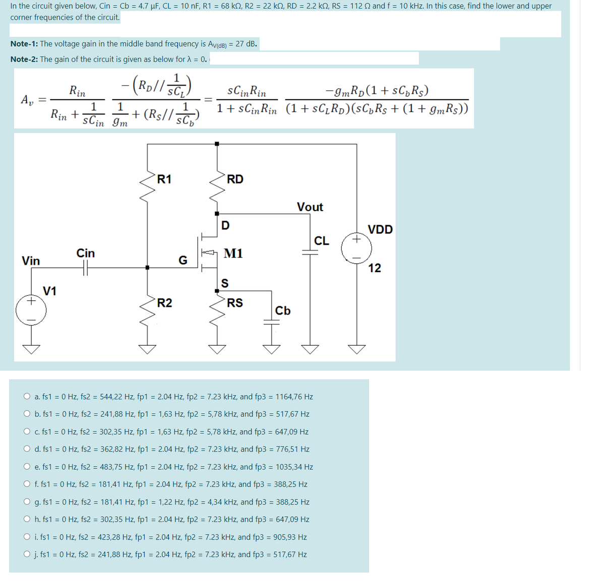
Transcribed Image Text:In the circuit given below, Cin = Cb = 4.7 µF, CL = 10 nF, R1 = 68 kN, R2 = 22 k2, RD = 2.2 kN, RS = 112 Q and f = 10 kHz. In this case, find the lower and upper
corner frequencies of the circuit.
Note-1: The voltage gain in the middle band frequency is AvidB) = 27 dB.
Note-2: The gain of the circuit is given as below for A = 0.
(Rp//SCL
sCinRin
1 + sCinRin (1 + sC_Rp)(sC„Rs + (1+ gmRs))
-ImRp (1+ sC,Rs)
Rin
1
1
Rin +
sCin Im
1
+ (Rs// 5C
R1
RD
Vout
D
VDD
CL
Cin
M1
Vin
G
12
S
V1
+
R2
RS
Cb
O a. fs1 = 0 Hz, fs2 = 544,22 Hz, fp1 = 2.04 Hz, fp2 = 7.23 kHz, and fp3 = 1164,76 Hz
O b. fs1 = 0 Hz, fs2 = 241,88 Hz, fp1 = 1,63 Hz, fp2 = 5,78 kHz, and fp3 = 517,67 Hz
O c. fs1 = 0 Hz, fs2 = 302,35 Hz, fp1 = 1,63 Hz, fp2 = 5,78 kHz, and fp3 = 647,09 Hz
O d. fs1 = 0 Hz, fs2 = 362,82 Hz, fp1 = 2.04 Hz, fp2 = 7.23 kHz, and fp3 = 776,51 Hz
O e. fs1 = 0 Hz, fs2 = 483,75 Hz, fp1 = 2.04 Hz, fp2 = 7.23 kHz, and fp3 = 1035,34 Hz
O f. fs1 = 0 Hz, fs2 = 181,41 Hz, fp1 = 2.04 Hz, fp2 = 7.23 kHz, and fp3 = 388,25 Hz
O g. fs1 = 0 Hz, fs2 = 181,41 Hz, fp1 = 1,22 Hz, fp2 = 4,34 kHz, and fp3 = 388,25 Hz
O h. fs1 = 0 Hz, fs2 = 302,35 Hz, fp1 = 2.04 Hz, fp2 = 7.23 kHz, and fp3 = 647,09 Hz
O i. fs1 = 0 Hz, fs2 = 423,28 Hz, fp1 = 2.04 Hz, fp2 = 7.23 kHz, and fp3 = 905,93 Hz
O j. fs1 = 0 Hz, fs2 = 241,88 Hz, fp1 = 2.04 Hz, fp2 = 7.23 kHz, and fp3 = 517,67 Hz
수
Expert Solution
This question has been solved!
Explore an expertly crafted, step-by-step solution for a thorough understanding of key concepts.

Step by step
Solved in 2 steps with 2 images

Knowledge Booster


Learn more about
Need a deep-dive on the concept behind this application? Look no further. Learn more about this topic, electrical-engineering and related others by exploring similar questions and additional content below.Recommended textbooks for you
Introductory Circuit Analysis (13th Edition)
Electrical Engineering
ISBN:
9780133923605
Author:
Robert L. Boylestad
Publisher:
PEARSON

Delmar's Standard Textbook Of Electricity
Electrical Engineering
ISBN:
9781337900348
Author:
Stephen L. Herman
Publisher:
Cengage Learning

Programmable Logic Controllers
Electrical Engineering
ISBN:
9780073373843
Author:
Frank D. Petruzella
Publisher:
McGraw-Hill Education
Introductory Circuit Analysis (13th Edition)
Electrical Engineering
ISBN:
9780133923605
Author:
Robert L. Boylestad
Publisher:
PEARSON
Delmar's Standard Textbook Of Electricity
Electrical Engineering
ISBN:
9781337900348
Author:
Stephen L. Herman
Publisher:
Cengage Learning
Programmable Logic Controllers
Electrical Engineering
ISBN:
9780073373843
Author:
Frank D. Petruzella
Publisher:
McGraw-Hill Education

Fundamentals of Electric Circuits
Electrical Engineering
ISBN:
9780078028229
Author:
Charles K Alexander, Matthew Sadiku
Publisher:
McGraw-Hill Education

Electric Circuits. (11th Edition)
Electrical Engineering
ISBN:
9780134746968
Author:
James W. Nilsson, Susan Riedel
Publisher:
PEARSON

Engineering Electromagnetics
Electrical Engineering
ISBN:
9780078028151
Author:
Hayt, William H. (william Hart), Jr, BUCK, John A.
Publisher:
Mcgraw-hill Education,