In the circuit in the figure, Rs = 3.8 kohm, R₁ = 82 kohm, R₂ = 22 Kohm, Rc = 5.6 Kohm, RE = 1.5 k and R₁ = 3.3 k and B = 150. Since the capacitances are C1 = 0.5 µF and C2 = 0.8 µF, what is the low cutoff frequency of the given circuit? NOTE-1: In the middle band frequency, B = 150 will be taken and frequency dependence of B will not be taken into account. NOTE-2: The output impedance of the transistor will be neglected in ro calculations.
In the circuit in the figure, Rs = 3.8 kohm, R₁ = 82 kohm, R₂ = 22 Kohm, Rc = 5.6 Kohm, RE = 1.5 k and R₁ = 3.3 k and B = 150. Since the capacitances are C1 = 0.5 µF and C2 = 0.8 µF, what is the low cutoff frequency of the given circuit? NOTE-1: In the middle band frequency, B = 150 will be taken and frequency dependence of B will not be taken into account. NOTE-2: The output impedance of the transistor will be neglected in ro calculations.

Power System Analysis and Design (MindTap Course List)
6th Edition
ISBN:9781305632134
Author:J. Duncan Glover, Thomas Overbye, Mulukutla S. Sarma
Publisher:J. Duncan Glover, Thomas Overbye, Mulukutla S. Sarma
Chapter3: Power Transformers
Section: Chapter Questions
Problem 3.30P: Reconsider Problem 3.29. If Va,VbandVc are a negative-sequence set, how would the voltage and...

Related questions
Question
In the circuit in the figure, Rs = 3.8 kohm, R₁ = 82 kohm, R₂ = 22 Kohm, Rc = 5.6 Kohm, RE = 1.5 k and R₁ = 3.3 k and B = 150. Since the capacitances are C1 = 0.5 µF and C2 = 0.8 µF, what is the low cutoff frequency of the given circuit? NOTE-1: In the middle band frequency, B = 150 will be taken and frequency dependence of B will not be taken into account. NOTE-2: The output impedance of the transistor will be neglected in ro calculations.
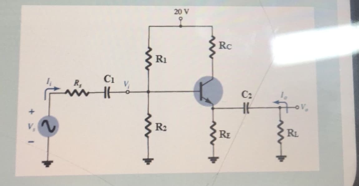
Transcribed Image Text:20 V
Rc
R1
Ci
R,
C2
R2
RE
RL
+
Expert Solution
This question has been solved!
Explore an expertly crafted, step-by-step solution for a thorough understanding of key concepts.

Step by step
Solved in 2 steps with 2 images

Knowledge Booster


Learn more about
Need a deep-dive on the concept behind this application? Look no further. Learn more about this topic, electrical-engineering and related others by exploring similar questions and additional content below.Recommended textbooks for you
Power System Analysis and Design (MindTap Course …
Electrical Engineering
ISBN:
9781305632134
Author:
J. Duncan Glover, Thomas Overbye, Mulukutla S. Sarma
Publisher:
Cengage Learning
Power System Analysis and Design (MindTap Course …
Electrical Engineering
ISBN:
9781305632134
Author:
J. Duncan Glover, Thomas Overbye, Mulukutla S. Sarma
Publisher:
Cengage Learning