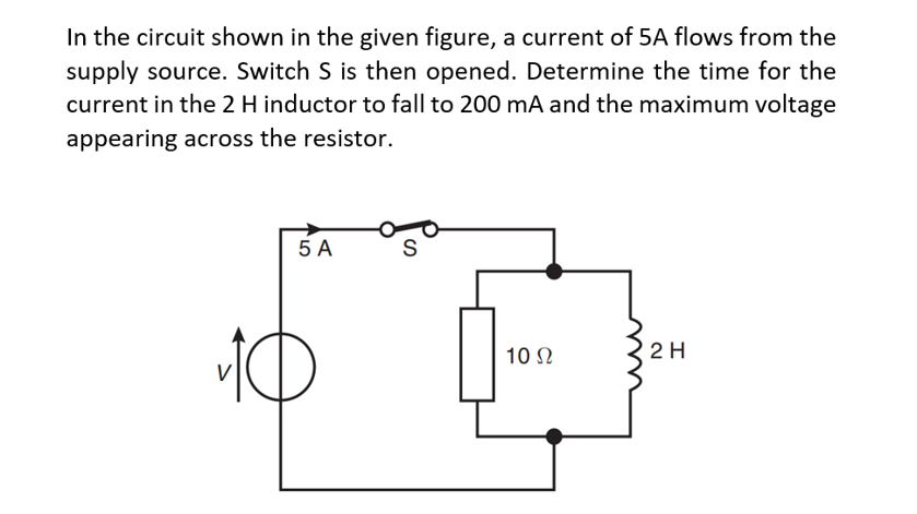
In the circuit shown in the given figure, a current of 5A flows from the supply source. Switch S is then opened. Determine the time for the current in the 2 H inductor to fall to 200 mA and the maximum voltage appearing across the resistor. 5 A 10 Ω 2 H
Q: The resultant of cross product of two vectors is a new vector perpendicular to .both of them True O…
A: We need to tell about whether the given statement is true or false.
Q: 3) Consider the system shown in Fig 3. a) What is the system type? R(s) K(s+1) s(s+4) (s+5) (s+2)…
A: Q. 3) Solution:- a) Type of a system is defined as the number of poles at origin of the open loop…
Q: SW1 B SW2 2 3 5 8 9 12 10 13 or A 0 0 1 1 11 C Logic function: Boolean equation for output, C = Step…
A:
Q: 6. If the total resistance is 4.950, find R. 252 M 100v + 3422 R N M 52 W 6.2 W 762
A:
Q: Convolve the following continuous-time signals, assuming that Th=1 sec, and T =1.5 sec Plot the…
A:
Q: Y(s) = What is the value of b? Blank 1 Add your answer 7s³ +2s² +3s −1 s² +3s +2 Blank 1 || a -9 s+2…
A:
Q: Calculate the following A. The resistance of each resistor B. The power in each resistor
A: Given- Source voltage, ET =120V Power = 200 Watt Resistance, RB = 2RA RC= 3RA To find- A. The…
Q: Given is the buck-boost(Cuk) converter with the following data: Input voltage Vg = 42 V Output…
A: Given Vg=42 V V0=24 V fs=200 kHz R =10 Ω
Q: Problem 10. For the double-beam oscilloscope dis- plays shown in Figure 10.20 determine (a) their…
A:
Q: Two point charges of equal magnitude and opposite sign are called electric dipole True O False O
A: In the given question we need to discuss about the electric dipole moment.
Q: A field effect transistor operates with a drain current of 100 mA and a gate-source bias of-1V. The…
A: Grain current = 100 mA Gate to source bias = -1V gfs = 0.25 We have to determine the change in drain…
Q: suppose a mile power at the input of receiver is 1nW in the bandwidth of interrest. What would be…
A:
Q: SW1 0 1 1 0 SW1 SW2 SW3 SW4 LSB O INPUTS SW2 SW3 0 1 0 0 0 1 1 1 Logic circuit function: 1 D 2 SW4 0…
A: Given: A logic circuit with four inputs, four outputs and one control signal A. Truth table of the…
Q: frequency of 1.5 kHz the open circuit impedance of a length of transmission line is 800∠−50◦ and the…
A: We need to find out characteristics impedance for given transmission line for given open circuit and…
Q: Example 14.52. An inductor of resistance 10 and inductance 100 mH is in parallel with a 10 nF…
A: Given: An inductor coil of Resistance : R=10 ohm and L=100 mH=0.1 H is in parallel with a 10nF…
Q: 1) Determine the bit rate and quantization step of the ADC in the sampling of analog signal with…
A: As per our company guidelines we are supposed to answer only first question kindly repost other…
Q: An analog signal is to be coded by an ADC. The signal contains significant frequencies up to 6MHz.…
A: We need to find out number of bits per sample, first we will find out the number of level then we…
Q: A dc shunt generator has a critical field resistance of 400 Q at 1200 rpm. Now if the speed of the…
A: Given a dc shunt generator has, Critical field resistance, Rc1=400 Ω. At critical speed, Nc1=1200…
Q: For an n-channel JFET, IDss=3 mA, VGs(om)=-6V. Determine the forward transconductance for VGs=-4V.
A:
Q: The Fourier transform of a continuous-time function x(/) is X () = -Find the Fourier transform of…
A:
Q: 3. Determine 1₁ and 12 using current division. 12 2010 ent from our this 152 2002
A: Given: Required: I1 and I2
Q: 2. Design a clamper circuit to perform the function indicated. Vin th DESIGN Si diodes 10 V -10 V +…
A: In this question we need to design a clamer circuit.
Q: it is an Level triggered digital circuit whose basic function is memory and is capable of storing a…
A: In this question, We are discussing about the level triggered digital circuit. Triggering is used…
Q: Q36. A resistor with a current of 3 A through it converts 500 J of electrical energy to heat energy…
A:
Q: (coso) (47) find the Power factor of the following ckf.
A: It is given that:
Q: Use mesh analysis to find I₁, I₂ and 13. 1' 15 V +1 I, + Vo§222 4529 12 SA 13 1002 2V0
A: By using of mesh analysis we will find out the mesh current for given circuit
Q: In the circuit shown in the given figure, a current of 5A flows from the supply source. Switch S is…
A: We need to find out the inductor current and voltage across resistor in the given circuit . We will…
Q: Problem 10. For the double-beam oscilloscope dis- plays shown in Figure 10.20 determine (a) their…
A:
Q: Prove the following relationship mathematically between the steps of the solution in detail: N=N₁…
A: Given: Proof of N=NCexp-Eg2kT.
Q: The external load characteristic of a DC generator at rated speed is assumed to be linear and is as…
A: Given characteristics of a DC generator. Load current IL = 50A Asked to find the load circuit…
Q: 10. both inputs of a NAND LATCH are low, then the S input goes HIGH . shortly thereafter, the R…
A:
Q: Electrical equipment in an office takes a current of 13A from a 240V supply. Estimate the cost per…
A: Current I = 13 A Voltage V = 240 V Time = 30 hours Cost = 13.56p
Q: A 250 V transformer takes a current of 0.5 mA with a power factor at no-load of 0.3 lagging.…
A:
Q: SUL A SW2 B 1 2 7486N 3 C L1 Record the state in the appropriate space in the Table. Study the truth…
A: Here we are given a circuit with following elements XOR gate Not gate LED Steps to solve the…
Q: A transmission line has a reactance of 1 Pu is operating at Vs = Vr = 1 Pu. The generator is…
A: Given: Reactance = 1 PuVs=Vr= 1 PuPactive = 0.5 Pu Find: Load Angle ( δ ) = ?
Q: A SW1 B SWZ 2 5 6 8 9 12 10 13 or A 0 0 1 1 11 C Logic function: Boolean equation for output, C =…
A:
Q: A 10 ohms and a 20 ohms resistance are connected in parallel and a 5 ohms is connected in series…
A:
Q: Electrical equipment in an office takes a current of 13A from a 240V supply. Estimate the cost per…
A:
Q: 5. Find Vo using source transformation. ба 652 W Vo W 50 + 3A 15.2 n + $100 30V ✓7A
A:
Q: Accuracy of an instrument or device is the difference between the indicated value and actual value.…
A:
Q: the fourier transform of a rect * function is O sine O sinc O rect An energy signal has G(f) = 10. *…
A: We need to select correct option for Fourier transform of rect function and we need to select…
Q: Example 12.36. A capacitor of capacitance 10 uF has a loss angle of 10° at 50 Hz. Find (i) power…
A: Given: C =10 μfδ = 10∘f = 50 Hz Find:. Power Factor Angle φcPower Factor cosφc
Q: H(z) -1 1 - 지 (1 − ¼z−¹)(1 + ¼z−¹)
A:
Q: Given Figure shows the input characteristic for an n-p-n silicon transistor. When the base emitter…
A: Base current fluctuation with base-emitter voltage is an input characteristic. The fluctuation of…
Q: Obtain the Fourier transform of the "switched-on" exponential function shown in Fig. 18.7. f(t) 0…
A: Given:
Q: MESH ANALYSIS 4. Find the currents i₁, i2, and i3. 12 V 4Ω www 12 www 632 10 V www 202
A:
Q: The impulse function is :denoted by S(t) O u(t) O h(t) O u(t) or 8(t)
A: We are authorized to answer one question at a time, since you have not mentioned which question you…
Q: 4 thyristors rated 200 V in series. The operating voltage of the string is 600 V. Derating factor of…
A: Given, Total number of thyristor, n = 4. Thyristor rated voltage = 200 V. Operating voltage = 600 V.
Q: 5. Determine v using source transformation. Show detailed circuit transformation and resistance…
A: We need to find out unknown voltage for given circuit by using of source transformation .
Q: 5A V3 O a. 5v1 Ob. 201 www O c. 5v₁ - 492 202 w www Pi V2 2v3 = -2 5v₂ + 2V3 ww = V2 - 2v3 = 4 Od.…
A:
Step by step
Solved in 2 steps with 1 images
- Three capacitors having capacitance values of 20F,40F, and 50F are connected in parallel to a 60 - Hz power line. An ammeter indicates a circuit current of 8.6 amperes. How much current is flowing through the 40F capacitor?A series RL circuit consisting of a single resistor a single inductor is being supplied by a 20 volt battery. The circuit is currently open and has a initial current of 0 A. The resistor has a resistance value of 100 ahms. If the current flowing through the circuit 1.5 sec after closing the circuit is 0.15 A, find the value of inductanceHow can four 100 kΩ resistors be connected so that the equivalent resistance of the four equals 250 kΩ? Sketch the arrangement, describe the resistor arrangement in words, and justify your picture by calculating the equivalent resistance. Repeat this part of the question with four 100 F capacitors and an equivalent capacitance of 75 F.
- An inductor of 5H, a resistor of 20ohms, and a capacitor of 20mF are connected in series with a source of E=10cos2t V. At t=0, the charge on the capacitor and current in the circuit is zero. Find the charge and current at any time t.The circuit shown in the attached image contains a voltage source with emf ε = 2.99 V, a resistor with resistance R = 135 kΩ, and a capacitor with capacitance C = 612 nF. When switch S is set to position a, the three circuit elements are in series. When the switch is in position b, the battery is excluded from the circuit. The switch is initially moved to position a, where it remains for a sufficiently long time that the capacitor is fully charged. The switch is now moved to position b. What is the magnitude of the instantaneous current, in amperes, through the resistor the instant the switch makes contact with terminal b? With time meausred the instant that switch S is closed in position b, calculate the time, in seconds, when the charge on the capacitor is one-half of its maximum value. Calculate the current through the resistor, in amperes, at time t = 155.5 ms after the switch is closed in position b.To what circuit element does a very large (ideally, infinite) inductance having an initial current of 10 A correspond? Explain your answer.
- Determine the equivalent capacitance of each of the circuits in the figure shown. Note: I leave the image of the exercises in Spanish, but it is easy to understand. Also in the other image is the correct final answer, for checking. IMPORTANT:Please, preferably the procedure should be digital, not on paper.This way I understand better.I would appreciate it very much!For this problem, there is no initial energy present in the system, and you may assume the passive sign convention. The voltage across a 27mH inductor is given by the function below. What is the current through the inductor a very long time after t=10 seconds? Express your answer to the nearest 0.01 Ampere, but do not enter the unit. v(t)=100 δ(t-10)mV.( need only handwritten solution .otherwise downvote.)In this circuit, the capacitance of the capacitor is 1 F, the resistance of the resistor is 1 Ohm, and the battery voltage = 1 V. When the switch is moved from a to b at time t=0, the amount of electric charge stored in the capacitor at t=1 second is approx.. .C.
- Determine the equivalent capacitance of each of the circuits in the figure shown. Note: I leave the image of the exercises in Spanish, but it is easy to understand. Also in the other image is the correct final answer, for checking.Referring to the circuit in the figure shown, calculate the value of R that will make the energy stored in the capactior equal to that stored in the capacitor equal to that stored in the inductor under dc conditions. Note:In the attached images, the exercise is in Spanish and is easier to understand. There is also the final correct answer, to check the answer.A 1-H inductor is connected in series with a 6-ohm resistor. If the connection is energized from a 9-V DC source, determine the current (in amperes) through the circuit for a long time. The initial current is 100 mA. Express your answers accurate to four decimal places. No need to put the units.