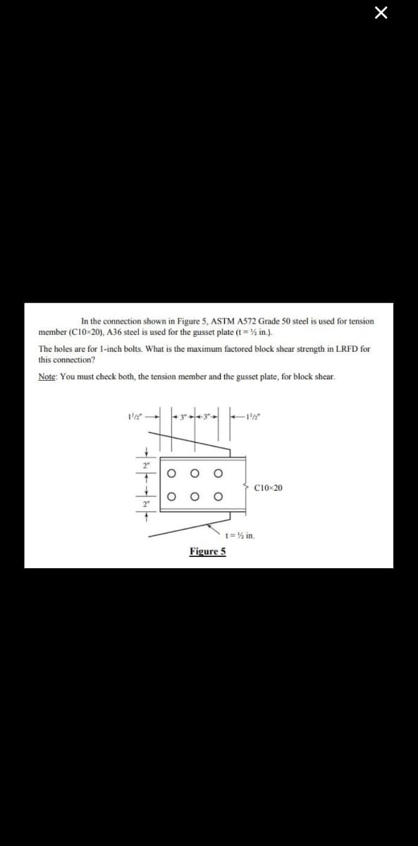
In the connection shown in Figure 5, ASTM A572 Grade 50 steel is used for tension member (C10-20), A36 steel is used for the gusset plate (t = ½ in.). The holes are for 1-inch bolts. What is the maximum factored block shear strength in LRFD for this connection? Note: You must check both, the tension member and the gusset plate, for block shear.
Q: A block of wood 50cm in diameter with s = 0.95 is immersed in a liquid with s = 1.05. Determine the…
A:
Q: Q5-): A city discharge 6 mgd of treated wastewater ,containing (7 mg/l) of phosphorus and (20 mg/l)…
A: We must account for the contributions from each source independently in order to determine the…
Q: Through a very narrow gap of height 'h a thin plate of large extent is pulled at a velocity V. On…
A: Given- The given situation of the question is shown below in the diagram- It is needed to find the…
Q: A 4-hour rainfall in a catchment of 250 km² produces rainfall depths of 6.2 cm and 5.0 cm in…
A:
Q: A child and a sled with a combined mass of 50.0 kg slide down a frictionless slope. If the sled…
A:
Q: Direction: A four hour unit hydrograph of a catchment is traingular in shape with base of 80 hours.…
A: 4 hour Unit Hydrograph triangular in shape Base=80 hours Area=720 km2 Base flow=30 m3/s Phi-index=1…
Q: Calculate the maximum tensile and compressive stresses in the section of BC of the beam. 15 ເຄດາ -…
A:
Q: Can just certain candidate system types be employed in a building?
A: A candidate system refers to a proposed solution for a particular aspect of a construction project.…
Q: ompute the vertical distance based on the following con
A:
Q: Draw the internal force diagrams of the given structure. Use E= 200GPa, I = 95e8mm*, A=1000mm². 20…
A: Find: (a) Axial Force in ab (b) Maximum moment in the structure
Q: Define the following words Tesserae Kline Klismos Chai
A: These three terms give various elements that are important in design and art. Learning these will…
Q: And the void ratio for each load increment is shown in the table below. σ₂ (kPa) Void ratio 15 1.66…
A: Vertical pressure, kPa Void ratio, e 15 1.66 30 1.65 60 1.64 120 1.52 240 1.38 480 1.25…
Q: Simply supported beam of Length 16m Subjected to dead Load 5 KNlm and Live Load greater than span as…
A: Span, L = 16 m Dead Load, DL = 5 kN/m Live Load, LL = 8 kN/m To find: 1. The maximum shear force at…
Q: PROBLEM # 2: 15 A VESSEL CYLINDRICAL 0.24 INCHES DIAMETER 0.96 m. IF IT 19 UNCOVERED AT THE 1.44 m…
A: Diameter of closed cylindrical vessel, d= 0.24in=0.0060m, Length of Vessel, l= 1.44m Rotation, N =…
Q: What is the correct rod reading at A with the instrument set up at B? Refer to Table 3.
A: To find correct rod reading at A with the instrument set up at B
Q: A strip footing founded on dense sand (p=35° from direct shear tests and yar-17kN/m³), is to be…
A:
Q: The average rainfall for a 3 hour duration storm is 2.7 cm and the loss rate is 0.3 cm/hr. The flood…
A: Duration of storm- 3 hour Average rainfall=2.7 cm, Base flow=20 m3/s, Peak flow = 210 m3/s, Loss…
Q: 4 10 20 50 80 120 200 Pan 6.0 g 35.847 69.685 32.144 12.798 22.885 15.974 9.563 9.112
A: According to Indian Standard Soil Classification System (ISSCS), soil with particle size > 300 mm…
Q: Using Unit Load Method to find the Load (P kN) to make the vertical deflection at point (B) equal to…
A: The beam figure is given in question.
Q: Question 2: Calculate the centroid, (x, y), in a different way than used in question 1 by either…
A: To find location of centroid
Q: Direction: An activated sludge system (sketched below) is operating at equilibrium with the…
A:
Q: A full hemispherical container with its radius as written in the figure has its water flowing out…
A: Coefficient of Discharge ,C=0.6 , Diameter ,D= 50mm , Radius, r=25mm To Find : Depth of water…
Q: A timber beam is 100 mm wide and 150 mm deep. The beam is simply supported and carries a central…
A: Given- A timber beam- width=100 mm, depth=150 mm, Simply supported beam- central concentrated load=W…
Q: Air is flowing in pipe as shown in figure. If u = 10 m/s, the manometer reading is (use g = 10 m/s²,…
A: Initial velocity u=10 m/s, g=10 m/s2, Density of air- ρ=1.2 kg/m3, It is needed to find the value…
Q: Requirements: Shear and Moment with diagrams Using slope deflection method
A: Draw shear force and bending moment diagram using Slope-Deflection Method.
Q: 3)/ Three clay specimens, having small air-voids content were tested in a shear box under undrained…
A: Given; σ1 =1 σ2=2 σ3 = 3 in (kg/cm2)τ1 = 0.9 τ2 = 1.01 τ3 = 1.12 in (kg/cm2)
Q: A hydraulic jump occurs in a rectangular channel 2.3 m wide with a flow rate of 1.5 m^3/s. If the…
A: Given; Width (B) = 2.3 m Flow rate (Q) = 1.5 m³/s Upstream depth (y1) = 0.25 m
Q: Two observation wells penetrated into a confined acquifer and located 1.5 km apart in the direction…
A: Two observation wells- Distance s=1.5 km=1.5×1000 m=1500 mHead=45 m & 20 m.k=30 m/day,porosity…
Q: A 4-hour rainfall in a catchment of 250 km² produces rainfall depths of 6.2 cm and 5.0 cm in…
A:
Q: Question A traffic stream in particular direction of a two-lane road moving with a constant speed of…
A: A traffic stream in particular direction- 2 lane road-Speed V=50 kmphAverage headway t=2.52 sTo…
Q: Determine the spacing between stirrups at maximum shear force for the simply supported beam that has…
A: Since the beam is symmetrically loaded we get equal reaction at supports RL = RR = Wu*L2 Wu =…
Q: A 2-minute error in reading an angle means that a point that is set 50 feet away is off by 1. 0.29…
A:
Q: A 1-h rainfall of 10 cm magnitude at a station has a return period of 50 years. The probability that…
A:
Q: Draw the shear moment diagrams of the following problems 8 kN/m 1.5 m- 1.5 m- 6 kN
A: Draw shear force and bending moment diagram of the beam. Note: As per our guidelines we are…
Q: If velocity is zero over 1/3rd of a cross section and is uniform over remaining 2/3rd of the…
A:
Q: Q/Draw SFD and BMD 2m 12 N/m OLB 1m 40 N
A:
Q: The sum of the moments about point A due to the forces and couples acting on the bar is zero. a)…
A: Sum of forces and couple about A = 0 Couple at A = 20 kNm Vertical force at A = 5 kN Horizontal…
Q: Problem 4. The Warren truss loaded as shown in the figure supported by a roller at B and a hinge at…
A: Determine the force in member BC, DF and BE using Method of Section.
Q: For the loaded beam shown below , E
A:
Q: The effective shear strength parameters of a normally consolidated clay are p= 25° and c= 0. A…
A: In consolidated undrained test The cell pressure, σ3= 112kPa The deviator stress, σd= 10kPa To…
Q: 10. Determine the reactions at supports. A is pin support ans B is roller 18 ft 2.5 k/ft A -12 ft-…
A: A loaded frame is given and it has been asked to determine support reactions, please refer below…
Q: Assign the vehicle trips shown in the origin-destination trip table to the network, using the…
A: While going from one node to other node, the path is decided based on the minimum travel time in…
Q: Determine the reactions at support A and D. Assume A is a pin and B is a roller 800 lb 30° -10 ft- B…
A:
Q: PROBLEM # 31 THIRDS THE 9.7 How SPILLED VERTICAL POINT b. IF CENTER FULL FAST AT? OF of CYLIN PRICAL…
A: Based on the given data, we need to first determine the volume of air formed after spillage. Volume…
Q: A normally consolidated clay layer settles 1 cm when the pressure increases from 1 kg/cm² to 2…
A:
Q: Find the support reactions and joint force of the construction. shown on the figure, if M=10 kNm and…
A:
Q: 15.6 Solve Problem 15.2 for the loading shown in Fig. P15.2 and a settlement of in. at support B.…
A: Given: E = 29000 ksi=201.3876 ksf I = 1650 in4 = 0.07957 ft4 The settlement, h = 0.5 in Analyze the…
Q: The reaction of the ground is uniformly distributed. Draw the shear and bending moment diagram for…
A: ###Calculation for SF and BM and Drawing of SFD and BMD ####
Q: For the structural loading shown in Figure 1, draw the shear and bending moment diagram complete…
A:
Q: A sign is required to be put up asking drivers to slow down to 30 km/h before entering Zone Y (see…
A: The condition is shown in the figure- Slow down speed =30 km/h, Distance required to slow down =174…
Trending now
This is a popular solution!
Step by step
Solved in 3 steps with 2 images
- Two steel plate tension members have been connected using 0.72 inch diameter bolts arranged in an equally-spaced 9 by 3 rectangular formation. Both plates have a thickness equal to 1/3 in. Take shear fracture stress as 51.2 ksi, clear distance for each edge bolt as 0.12 in, and the clear distance for the other bolts as 1.072 in. a)Sketch the connection showing all the details and measurements with units. b)Find the maximum allowable service dead load and live load assuming live load is half as much as dead load. Consider ASD.For the splice connection shown in the figure, a. Check all spacing and edge-distance requirements. (For 1-in diameter bolts minimum edge distance is 1.25 in. AISC Table J3.4) b. Compute the design strength based on shear and bearing. (Use LRFD) The plates are PL 1/2" x 7" steel ASTM A36 (Fy = 36 ksi, Fu = 58 ksi) and the bolts are 1-in diameter A325X (Fnv = 60 ksi) in standard holes.Use ASD to determine the width of the 5/8 inch thick A36 plate subjected to tension as shown below. The dead load effect is PD=85 kip while the live load effect is PL=80 kip. Two rows of 5/8 inch standard bolts will be used for the connection and the plate width can be manufactured in 1 inch increments. Assume that the larger connected plate does not fail. Consider the limit states of gross tensile yield and tensile rupture. Find the required tension strength, Pa, for the controlling ASD load combination. Determine the width necessary for the plate to resist gross tensile yield. Determine the width necessary for the plate to resist tensile rupture. Report the required plate width.
- A 1 ⁄2 × 5-inch plate of A588 steel is used as a tension member. It is connected to a gusset plate with four 5 ⁄8-inch-diameter bolts as shown in Figure 1. Assume that the effective net area Ae equals the actual net area An. (a) Calculate the design strength for LRFD? (b) Calculate the allowable strength for ASD?A double lap splice connection shown in figure B is made up of 6mm x 150mm and 9mm x 150mm. Use NSCP specifications and assume a double row of bolts with standardsize holes for a bearing type connection with threads excluded from the shear planes.Minimum tensile strength Fu = 552.93MPa. Assume diameter hole is 3mm bigger than thediameter of bolts. Allowable shear stress is Fv = 207MPa. Allowable bearing stress fb = 1.2Fu.Diameter of bolts is 19mm. Fy = 449.25MPa.(a) Compute the tensile capacity of the steel plates. (Max. Net Area = 0.85 of Gross Area)(b) Compute the number of 19mm diameter bolts to develop the full strength of the plates. Note: SHOW DRAWINGS AND SOLUTIONS.Two plates each with thickness t = 5 mm are bolted together with 6 - 22 mm diameter bolts forming a lap connection. Plate (A36): Fy = 248 Mpa FU = 400 MPa bolts are A325 in standard holes with threads excluded from shear planes. Considering Tension Rupture, compute the the design strength for LFRD. Use NSCP 2015
- the design shear strength phi rnv of one A325-X bolt (Group A, X type), 7/8 inch in diameter in double shear is equal to: 46.8 kips 30.7 kips 27.9 kips or 61.3 kipsConsider the tension member shown below. The channel is made of ASTM A572 (Fy = 50 ksi; Fu = 65 ksi), and is connected to a 3/8-inch thick gusset plate made of ASTM A36 steel (Fy = 36 ksi; Fu = 58 ksi). The bolts are 7/8 inch in diameter, made of ASTM A307 bolts. The bolted connection is bearing-type. (a) Check if the given connection follows the code provisions on spacing and edge distance limits. (b) Determine the maximum allowable service tensile load that the member is allowed to carry. Consider all applicable limit states for tension member and connection. Consider only block shear and bearing limit state for gusset plate. Use ASD specifications. use AISC book (3decimals) PLEASEEE.Consider the tension member shown below. The channel is made of ASTM A572 (Fy = 50 ksi; Fu = 65 ksi), and is connected to a 3/8-inch thick gusset plate made of ASTM A36 steel (Fy = 36 ksi; Fu = 58 ksi). The bolts are 7/8 inch in diameter, made of ASTM A307 bolts. The bolted connection is bearing-type. (a) Check if the given connection follows the code provisions on spacing and edge distance limits. (b) Determine the maximum allowable service tensile load that the member is allowed to carry. Consider all applicable limit states for tension member and connection. Consider only block shear and bearing limit state for gusset plate. Use LRFD specifications. use AISC book
- A double-angle shape is shown in the figure. The steel is A36, and the holes are for 1/2-inch-diameter bolts. Assume the Ae = 0.75An.a) Determine the allowable tensile strength for ASD.b) Determine the design tensile strength for LRFD.The design shear strength phi rnv of one A490 X-bolt, 3/4 inch in diameter (Group B, X type) in single shear is equal to: Group of answer choices 39.8 kips 66.2 kips 27.8 kips 55.7 kipsA C15x40 channel section is bolted to a gusset plate is used to resist a tensile loadPu =313 k. The bolts are 3/4 inch diameter bolts A325 N (Group A, N Type) used insingle shear to resist this load. The bolts are to be symmetric and arranged in 3 rows.1) Determine the number of bolts needed for this connection. Draw a detailshowing how the bolts are arranged and showing spacing and edge distances onthis connection. Assume edge distance Le = 1.75db , use Le to nearest 1/4 in.2) If the connection is to be replaced by a fillet welded connection with transversewelds only along the channel web, determine the required fillet size to thenearest 16th of an inch.