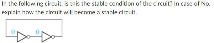
In the following circuit, is this the stable condition of the circuit? In case of No, explain how the circuit will become a stable circuit.


Q: 2. Use a ROM to implement a digital circuit that accepts a three-bit binary number A=a2a1a and…
A: I have given correct answers and proper explanations for the given questions with a Diagram and…
Q: For the following parallel resonant circuit: Ground + VIN R₁ www m J C₁ If R1 = 2 Ohms, L1 = 1 H,…
A:
Q: Q3: Given the sequence x(n) = [0.8, 0.6, 0.4, 0.2]. a) Compute its spectrum using DFT X(k). b)…
A:
Q: NO AI, ANSWER STEP BY STEP PLZ
A: Step 1:PLEASE VOTE UP IF YOU LIKE THE SOLUTIONTHANK YOU
Q: The following is a band-rejection filter constructed from a series RLC circuit. ww R V C where Vi is…
A:
Q: (2) Find Va(t) given Vs(t) = 2√2 cos (4t+45°) V, and Is(t) = 0 A. 2 ww Va 0.25 H Vb (1/8) F Is(t)…
A:
Q: The current through a 25-mH inductor is 10e t/2 A. Find the power at t = 3 5. Enter your answer with…
A:
Q: R₁ 30 Xc₁ = 120 ww V₁ = 100 V XL₁ = 120 XC3= 120 Ω Xc₂ = 200 Ω XL₂-2002
A:
Q: Find ID and VD of the diode D1 and D2 byusing the CVD diode model (Assume Von = 0.7Vfor both…
A: KIRCHHOFFS CURRENT LAW: It states that the algebraic sum of currents entering into the node is…
Q: Calculate the time constant of the circuit shown. Enter your answer in units of microseconds Hint…
A: Step 1: To find the time constant of circuit using Thevenin's theorem. We remove inductor and…
Q: Can you provide me the detail answer about alexander electric circuits problem 4.48
A:
Q: None
A: A balanced load refers to a condition in an electrical system where the power consumed by each phase…
Q: The current through a 0.5 F capacitor is i(t) = 6(1 - et) A, with-t in seconds. Determine the power…
A:
Q: "I need the solution to be supported by an equation or inference."
A: Step 1: Step 2: Step 3: Step 4:
Q: 2a d 2b 20 Find the capacitance per meter of a single-phase transmission line. Assume d>>a and d>>b.…
A: If you are having doubt in any step please comment here. Thank you
Q: A source-free RC contains an initially charged capacitor with voltage Vo. What is the voltage across…
A:
Q: Please provide the truth table and circuit design for the following: Use D flip-flops to design a…
A: Step 1:Step 2:
Q: please draw a pmos reverse voltage protection circuit with a FDN308P, max voltage is 8.4V and max…
A: Schematic diagram of the PMOS reverse voltage protection circuit using the FDN308P MOSFET.Here's a…
Q: Question 16 The expression ABC + ABC + ABC can be simplified to: A BC+AC A BC BC + B C C D None of…
A: Given:A boolean expression, we need to select:Correct option for the simplified expression of the…
Q: If a J-type thermocouple is used in a standard two-junction thermocouple configuration with a 100°C…
A: Calculate V_(100/0): We have the equation: VT/100=30,mV. To find V100/0, we can use the Law of…
Q: 2. For the AC circuit below determine: a. the maximum current b. the resonant frequency c. power…
A:
Q: For the circuit below: (a) Find impedance Zt at resonance (b) Circuit voltage at resonance (c)…
A: The objective of the question is to find the total impedance at resonance, the circuit voltage at…
Q: A 400V three-phase, four wire dystem has the following loads connected: Phase 1: Load impedance Z1=…
A:
Q: (b) i(t) (t = 50ms is period of waveform b.) here is my answer i(t) = 10sin(125.66t + 120o)A can you…
A:
Q: In the figure below, R₁ = 9.00R, the ammeter resistance is zero, and the battery is ideal. What…
A: Step 1:Step 2:
Q: I need the expert solution and a detailed explanation of each step in the solution.
A: Build the Communication System Model:Utilize MATLAB's Simulink to create a model as depicted in the…
Q: The switch was closed for long time before it is opened at t = 0 s. Find indicated values and…
A: The objective of the question is to find the values of VR1(t), VR2(t), V₁(t), IL(t), and IL(t) +…
Q: (ii) For the circuit in Figure 2.0a: If v(t) = 10 cos(⍵t + 0º) volts, R = 510 Ω, and C = 0.22 µF;…
A: Step 1: Step 2: Step 3: Step 4:
Q: The switch was closed for long time before it is opened at t = 0 s. Find the initial and final…
A: The objective of the question is to find the initial and final conditions for VR₁(t), VR₂(t), V(t),…
Q: Question #4 18.9 Find the g parameters for the operational amplifier circuit shown in Fig. P18.9.…
A:
Q: QUESTION 1 What practical skills were taught and assessed in you Electronic Engineering lab? Choose…
A: A, B, D, and E are practical skills typically taught and assessed in an Electronic Engineering…
Q: Please answer in typing format
A: Step 1: as seen from circuit first we will finding out the voltage at point A as seen in the…
Q: Determine f, T, and amplitude for each of the following: a) v(t) = 75 sin(200πt) b) i(t) = 8…
A: Given: signals,a) v(t) = 75 sin(200πt)b) i(t) = 8 sin(300t) we need to determine:frequency f, time…
Q: The switch has been closed for a long time before opening at t = 0, where C₁ = 8F and C₂ = 4F.…
A: To solve this problem, we can use the principles of circuit analysis, particularly the equations…
Q: Please show how to determine the voltage using current or voltage dividers (as opposed to mesh…
A:
Q: For the circuit in Figure 3.0a: If v(t) = 10cos(⍵t + 0º) volts, R = 510 Ω, and L = 4.7 mH; use your…
A: Step 1:
Q: If the equivalent resistance is 4K ohm as seen by the source, show the steps to find this and the…
A:
Q: The swtich has been in position A for a long time and it is brought to position Batt=0s, making…
A: Since you have posted a question with multiple sub-parts, we will provide the solution only to the…
Q: Find the numerical expression for i,(t), and vo(t) when t≥ 0. t-0 C=200 μF 6mA 4K 20 4K www 18V
A: The circuit diagram,
Q: Simplify function F, with don't care conditions d given below, into a Product-of-Sums form. Show all…
A: To simplify the function ( F ) into a Product-of-Sums form, we need to use Karnaugh maps to identify…
Q: Do it
A: ANSWER:The correct answer is B) Two EXPLANTION:Option B) Two is correct because when four 1s are…
Q: Consider the given circuit. n 12+ R www www Rw Z.p a Le Vbn b Rw ww B For the balanced three-phase…
A: Given data: -PL=10 KWcosϕ=0.83Power loss in each wire =100 WVPH=400 VGiven circuit: -Find: -(RW)…
Q: The following circuit has been at DC steady state before the switch is closed at t=0. Let Vs1=30,-…
A:
Q: 100 K 2.5 V vo Given that k = 0.5 mA/V² and VTH = -1 V and λ = 0, fill up the table using the large…
A: Since you have posted a question with multiple sub parts and part (a) also contains multiple sub…
Q: The swtich has been in position A for a long time and it is brought to position B at t=0 s, making…
A: Given:with Vs=30 V and the switch has been in position in A for long time and it is connected to…
Q: no ai,
A: To derive the average bit error rate (BER) for noncoherent Binary Amplitude Shift Keying (BASK),…
Q: Q1: If X and Y are jointly continuous random variables with probability density function f(x,y)…
A: The covariance of the random variables X and Y is: Cov(X,Y)=[∫−11∫01xy(x+y) dx dy]−E(X)E(Y)…
Q: None
A: To perform small signal analysis for the given circuit, let's denote the transconductance of the…
Q: To =2+(3090+3090)/1e7 please help me ex7
A: We need to plot and in the same plot.where
Q: Upp fast
A:
Please answer in typing format

Step by step
Solved in 2 steps

- Find the number of nodes, closed paths (Loops), and branches in the given circuit. Draw the circuit, showing the number of nodes.Solve this circuit according to the given conditions in the question. Please solve this as soon as possibleFind the node voltages of the circuit in the figure and the current I
- Basic Electrical Engineering You are an electrician on the job. The electrical blueprint shows that eight 500-W lamps are to be installed on the same circuit. The circuit voltage is 277 V and is protected by a 20-A circuit breaker. Assuming that the load is continuous, is a 20-A circuit large enough to carry this load?Can you help explain how to do the attached problem: use the node-voltage method to solve for Vo in the circuit? And please provide the answer so I can see how to do it? Thank youCircuit theory Find the power of each source using the node voltage method in the circuit below. Specify whether the sources are supplying or dissipating power to the circuit.