Instruction/s: 1. Draw, Illustrate and label your schematic diagram before solving the problem. 4.) Given a Voltage -divider biased transistor circuit .Assume Beta DC is 100, ,Voltage at Base-emitter junction is 0.7v ,voltage at common collector is +15v, resistor RB1 is 10k ohms, resistor RB2 is 6k ohms, collector resistor is 1.5k ohms ,emitter resistor is 560 ohms. Determine base current ,collector current and voltage collector-emitter junction. These might help as a guide in answering the problem..
Instruction/s: 1. Draw, Illustrate and label your schematic diagram before solving the problem. 4.) Given a Voltage -divider biased transistor circuit .Assume Beta DC is 100, ,Voltage at Base-emitter junction is 0.7v ,voltage at common collector is +15v, resistor RB1 is 10k ohms, resistor RB2 is 6k ohms, collector resistor is 1.5k ohms ,emitter resistor is 560 ohms. Determine base current ,collector current and voltage collector-emitter junction. These might help as a guide in answering the problem..

Introductory Circuit Analysis (13th Edition)
13th Edition
ISBN:9780133923605
Author:Robert L. Boylestad
Publisher:Robert L. Boylestad
Chapter1: Introduction
Section: Chapter Questions
Problem 1P: Visit your local library (at school or home) and describe the extent to which it provides literature...

Related questions
Question
Instruction/s:
1. Draw, Illustrate and label your schematic diagram before solving the problem.
4.) Given a Voltage -divider biased transistor circuit .Assume Beta DC is 100, ,Voltage at Base-emitter junction is 0.7v ,voltage at common collector is +15v, resistor RB1 is 10k ohms, resistor RB2 is 6k ohms, collector resistor is 1.5k ohms ,emitter resistor is 560 ohms. Determine base current ,collector current and voltage collector-emitter junction.
These might help as a guide in answering the problem..
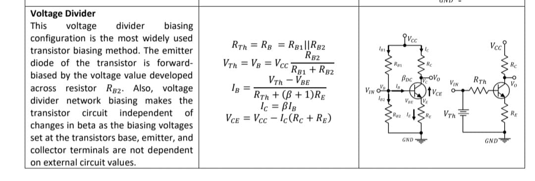
Transcribed Image Text:Voltage Divider
voltage
divider
biasing
configuration is the most widely used
transistor biasing method. The emitter
This
Vcc
RTh = RB = Rg1||RB2
RB2
Im
diode of the transistor is forward-
Vrh = VB = Vcc
Re
Rc
RB1 + RB2
Vrh – VBE
biased by the voltage value developed
across resistor RB2. Also, voltage
divider network biasing makes the
Boc oVo
VIN
Rth
Vo
IB =
RTh + (B + 1)RĘ
Ic = BIB
VCe = Vcc - Ic(Rc + RE)
VBE V
transistor
circuit independent
of
Rwa RE
R
changes in beta as the biasing voltages
set at the transistors base, emitter, and
collector terminals are not dependent
on external circuit values.
GND
GND
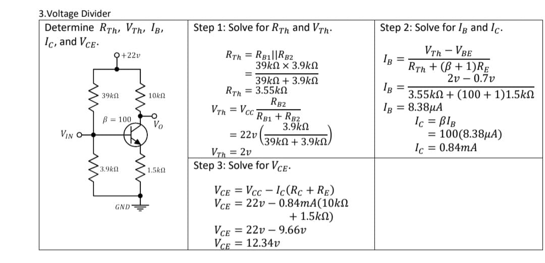
Transcribed Image Text:3.Voltage Divider
Determine RTh, Vrh, IB,
Ic, and Vce-
Step 1: Solve for RTh and VTh:
Step 2: Solve for Ig and Ic.
RTh = RB1||RB2
39kN × 3.9kN
VTh - VBE
RTh + (B + 1)RE
2v – 0.7v
O+22v
IR =
39kN + 3.9kN
Rrh = 3.55kN
RB2
IR =
3.55kN + (100 + 1)1.5kN
39kn
10kN
VTh = Vcc
IB = 8.38µA
RB1 + RB2
3.9kN
Ic = BlB
100(8.38µA)
Ic = 0.84MA
B = 100
Vo
VIN O-
= 22v
%3D
(39kN + 3.9kN,
VTh = 2v
3.9k
1.5kN
Step 3: Solve for VcE.
VCE
Vcc – Ic(Rc + RẸ)
GND=
Vce
= 22v – 0.84MA(10kN
+ 1.5kN)
VCE
= 22v – 9.66v
= 12.34v
Expert Solution
This question has been solved!
Explore an expertly crafted, step-by-step solution for a thorough understanding of key concepts.

Step by step
Solved in 3 steps with 2 images

Knowledge Booster


Learn more about
Need a deep-dive on the concept behind this application? Look no further. Learn more about this topic, electrical-engineering and related others by exploring similar questions and additional content below.Recommended textbooks for you
Introductory Circuit Analysis (13th Edition)
Electrical Engineering
ISBN:
9780133923605
Author:
Robert L. Boylestad
Publisher:
PEARSON

Delmar's Standard Textbook Of Electricity
Electrical Engineering
ISBN:
9781337900348
Author:
Stephen L. Herman
Publisher:
Cengage Learning

Programmable Logic Controllers
Electrical Engineering
ISBN:
9780073373843
Author:
Frank D. Petruzella
Publisher:
McGraw-Hill Education
Introductory Circuit Analysis (13th Edition)
Electrical Engineering
ISBN:
9780133923605
Author:
Robert L. Boylestad
Publisher:
PEARSON
Delmar's Standard Textbook Of Electricity
Electrical Engineering
ISBN:
9781337900348
Author:
Stephen L. Herman
Publisher:
Cengage Learning
Programmable Logic Controllers
Electrical Engineering
ISBN:
9780073373843
Author:
Frank D. Petruzella
Publisher:
McGraw-Hill Education

Fundamentals of Electric Circuits
Electrical Engineering
ISBN:
9780078028229
Author:
Charles K Alexander, Matthew Sadiku
Publisher:
McGraw-Hill Education

Electric Circuits. (11th Edition)
Electrical Engineering
ISBN:
9780134746968
Author:
James W. Nilsson, Susan Riedel
Publisher:
PEARSON

Engineering Electromagnetics
Electrical Engineering
ISBN:
9780078028151
Author:
Hayt, William H. (william Hart), Jr, BUCK, John A.
Publisher:
Mcgraw-hill Education,