iR(f) is(f)( 100 μF. 100 Ω is()-1 cos (200π)
Q: In the circuit of the figure below, the switch S has been open for a long time. It is then suddenly…
A: The given circuit is, Switch is opened for long time and then suddenly closed. E=10 VR1=57 ΩR2=105…
Q: For the circuit shown below the value of A is %3D R. R
A: Amplifier is an electronic device whose output is amplified version of the input signal. The…
Q: 2 For the figure below, if Vc = 362 sin(wt 33°) V, ic = 94 sin(wt + 57°) mA, and C = 2.2 µF, %3D…
A:
Q: damping ratio of § = 0.5, the value of rise time (tr) is equal to %3D 0.303 sec O 0.203 sec 0.403…
A: Given, A second order system with Natural frequency, ωn=6 radsec Damping ratio, ζ=0.5
Q: For the circuit in the figure, identify the correct expression for v when t> 0. Assume that v (0+) =…
A: V(t)=V(∞)+(V(0) - V(∞)) e-tτ V(0)=4 τ = RC R=2 C=100mF τ = 200 V(∞) = 0
Q: In the circuit shown in figure, after the switch is open for a long time, it is closed at t=0. Now,…
A:
Q: By using delta-star conversion, find the star resistance R1, R2, R3 theoretically.
A: According to the figure-: R13 = 50 ΩR12 = 100 ΩR23 = 100 Ω
Q: 8. 7.8 In the circuit , the voltage and current expressions are v=400e−5tV, t≥0+;i=10e−5tA, t≥0.2.…
A: Circuit diagram is given as, For RL circuit voltage is given by,
Q: Consider the given circuit under dc conditions, where R= 70. ww 2 F ЗА R 0.5 H NOTE: This is a…
A:
Q: The circuit shown is to be designed so that VL,dc =12V and VLr,p-p =2V. • mF 1. The required…
A: This circuit is full wave Rectifier with RC load. Capacitor is used as filter. Ripple voltage = 2V…
Q: 1. The waveforms x, y, and z are connected to the circuit presented in the figure below. Assuming…
A: This question requires timing diagram of the circuit and truth table of SR flip flop
Q: Write a small essay about transient state (RC and RL) then : For the circuit shown below, If the…
A:
Q: For the series RLC circuit shown in Figure, If L = 10 H, R = 400 Ohms and C = 100μF, vS(t) = 0, i(0)…
A: We have given a series RLC circuit below where;L=10HR=400ohmC=100μF=100×10-6FVst=Vs=0…
Q: In the circuit below, the switch was turned to the 2 position at t=0 after being in the 1 position…
A: In the given circuit, the switch at position at 1 for long time and moved to position 2 at t = 0.…
Q: Q1: For the circuits shown in figures. If the temperature has changed from 25°C to 65°C, find AIc.…
A:
Q: Consider the circuit shown below and answer all of the following questions. iR t = 0 10Ω V, = %3D 20…
A:
Q: Refer to the following figure. If IB=7S LA, BDC = 100, 43DI%3D VCC 20 V, and RC=15 kN the value of…
A:
Q: In the circuit below, the switch is closed for a long time before time t = 0. V, = 24V,R¡ = 3002, C1…
A:
Q: Q3: Impulse generator has 12 stages and contains 0.24 µF capacitors, the wave front resistance is 95…
A: An impulse generator is a device that generates extremely brief high voltage or high- current…
Q: EXAMPLE 4. Find i(t) if the circuit is in DC steady state prior to opening switch. i(t) ------> 10 V…
A: Given data, DC steady state Capacitor will be open circuited. Inductor will be short circuited.
Q: Given: V7, Is. Is 0.5 S 4Vz 0.125 S P2 Determine P. Determine P.
A: Find the power P1 and P2 If the voltage Vx=1V Current Is=6A
Q: A coil (RL) having a resistance of 15 ohms and inductance of 15H is connected in series with a 15…
A: we need to find out voltage across the coil.
Q: Q1: For the circuits shown in figures. If the temperature has changed from 25°C to 65°C, find Alc.…
A: Relation between Ic and Ico is given by :- IC=αIE + Ico here Ico is the reverse saturation current…
Q: Find the total energy stored in the circuit of Figure below 60 L = 2 mH 3Ω L = 4 mH %3D C = 20 µF C2…
A: To solve the above question, one should understand the behavior of inductor and capacitor in DC…
Q: 4. The circuit is in DC steady state at t =0". At t=0 the switch is opened. 24 V 0.25F
A: This question is from "Networks". Under which we are going to study about the transient response of…
Q: a. Sketch the root locus of the system shown in Figure Q8 when K varies from 0 to ∞. b. Determine…
A:
Q: 102 Q.13: The switch has been in position "1" for a long period of time and then at t=0 the switch…
A: First we will find differential equation governing the inductor current using KCL and KVL. we will…
Q: what the maximum values of RL in the circuit shown 100 Ω |10 V 5V Ο 1250 Ω 250 Ω Ο 500 Ω Ο 0.167 Ω +…
A:
Q: In the following figure, the switch is left in position a for a long time interval and is then…
A: According to the question, we have to find the rank and magnitude of Vs,VL, VR1,VR2.
Q: Find RAB in the circuit shown. 12 kQ A O 2 kQ 6 kQ RAB 4 kQ 12 k2 BO Select one: О а.2 К O b. 4 K O…
A:
Q: what the maximum values of RL in the circuit shown 100 Ω www 10 V 5V IZM = 30mA R₁
A:
Q: 20µF R + R3 Vc 0.5mH R2 10V 0.4mH 10µF 24V Assume the above circuit has been in this state for a…
A:
Q: 20µF R1 R3 Vc 0.5mH R2 10V 0.4mH 10μ 24V Assume the above circuit has been in this state for a very…
A: In steady state capacitor acts as open circuit and inductor acts as short circuit. Use kcl and kvl…
Q: The values of the components in the circuit are L = 163 mH, R, = 410 N, R, = 340 N, and E = 10.0 V.…
A: Fig: Given circuit (a) case 1 : when switch is closed at t =0 Although at t=0-…
Q: In the circuit shown in the Figure, if Vs = 12 V, R1 = 3 0, R2= 4 Q and R3 = 7 Q, the current i, at…
A: In this solution we discusses about transient analysis of RL circuit with source.
Q: The voltage phasor diagram for a certain series RLC circuit is shown in Figure below. Find the…
A: Step 1-Given:∆VL=193V∆VC=75V∆VR=124VTo find-∆Vmax(in volt)
Q: For the circuit shown in the Figure, the voltage v at t = 100 ms is: 5Ω %3D0 62 + v - 20 V 2 A 12 2…
A: Transient response is the response of a system which is the change in transient(equilibrium) or…
Q: Given circuit below and resistors value: Ra = 100 Q %3D Rb = 150 Q Rc = 200 2 %3D R. Rc Ro 2. 4…
A: Given circuit, And
Q: Find the time constant, - , for the following circuit. Include all steps. C, R, Vout C, R, Vin
A: In order to find the time constant of the system develope the transfer function for the given…
Q: Consider the following electrical circuite 100 µF t= 0 6 kN 12 V 6 kN 6 kN i. Find the respose time…
A: To find (i) response time (ii) Initial value of Capacitor (iii) Capacitor Voltage Vc(t) (iv) output…
Q: t=0 6 kN i(t) + i(t) v(t)=40 µF 30- 45 V(+)Vs 2 30kN O A) 1.5 mA O B) 7.5 mA ) 1.25 mA O D) OmA E)…
A: RESISTOR (R): A resistor is a passive electrical component with the primary function to limit the…
Q: Determine the current 7(1) in an RLC-circuit with resistance R = 802 %3D ductance L = 10 H ,…
A: RLC is series with the voltage E=240.5 sin10t Current in the RLC circuit. Inductive reactance XL…
Q: The circuit in the figure closes at t=0. 1 (t)? İ(t)? VI(t)? 200 V 552 0,05 H 40x10 F
A:
Q: In the circuit shown in the figure, the switch is closed at t = 0. Accordingly, find the value of…
A: The solution can be achieved as follows.
Q: Sketch the output voltage waveform vo(t) for the circuit shown and given the input voltage waveform…
A:
Q: The current of the circuit shown is: 150µF Select one: O a. 5.4A Ob. 2.4A O c. 4.6A O d. 3.7A Oe.…
A: Given circuit:
Q: In the circuit shown in the figure, the voltage vo(t) at t = 1 s is: 1H t=0 30 V U8 ww
A:
Q: 42 1 F0 Q.17: The switch has been in position "1" for a long time. At t=0, the switch moves to "2".…
A:
Q: the Electronic Circuit shown in the Figure. Rc RE vt= RBI V88 = 3V Zoom image 20 ohm, and RB1 =…
A:
Q: 102 Q.13: The switch has been in position "1" for a long period of time and then at t=0 the switch…
A:
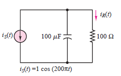
Find the current through the resistor in the circuit
shown in Figure
Step by step
Solved in 3 steps with 6 images
- Directivity of an antenna is 2.88 dB. If the antenna is transmitting at a wavelength of 1.9 cm, then what will be the effective aperture of the antenna.A citizen's 30MHz band radio is a half wavelength with 72Ω radiation resistance uses long antenna. If the antenna is 6.20mm in diameter and made of aluminum, the antenna Calculate the luminous efficiency. (Conductivity of aluminum ? = 3.5 × 10⁷ S / mThe maximum deviation of an FM channel allowed is 15.0 kHz at frequencies up to 3.6001 kHz. Using Carson’s rule, determine the bandwidth of the FM channel. Round the final answer to two decimal places. kHz
- What will be the maximum effective aperture of a microwave antenna whose directivity is 900.A Yagi-Uda antenna is designed to receive signals signals centered at 200MHz. Calculate the length of the reflector. (NEED A NEAT HANDWRITTEN SOLUTION ONLY OTHERWISE DOWNVOTE)Determine the critical frequency value of an HF signal if its maximum usable frequency is 7050.50 kHz at 35 degrees incidence.
- What is the frequency of a radio broadcast with a wavelength of 320 m? (Light travels at 3.10 ⁸ m / s in a free medium) A 4,89 MHz B 4,833 kHz C 206,89 kHz D 483,33 kHz E 937,5 kHzAn antenna has a loss resistance of 25 ohms, power gain of 30 and directivity of 42. Calculate the radiation resistance of the antenna.Please provide Handwritten answer. b) Sketch the root locus if C(s)=k. The root locus crosses the imaginary axis at s=1.6j rad/s.
- Assume that you wanted to transmit audio directly by antenna without modulation. If the signal to be transmitted has a frequency of 2 kHz, calculate the length of a quarter-wave vertical antenna. Explain why it is an impractical antenna.Microwave antenna has a wavelength of 22 meters and a directivity 35.Then the maximum effective aperture of the antenna assuming that the directivity is reduced by 50% .In the Figure given below calculate the X-ray intensity that reaches the detector. The linear attenuation coefficients at the effective X-ray energy of 68 keV are 0.2 cm-1 and 0.033 cm-1 for tissue and blood, respectively. 29.56 keV 129.56 keV 56.7 keV 200 keV