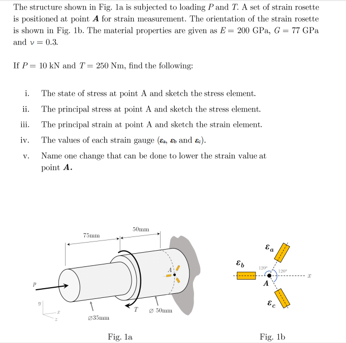
is positioned at point A for strain measurement. The orientation of the strain rosette is shown in Fig. 1b. The material properties are given as E = 200 GPa, G = 77 GPa and v = 0.3. If P = 10 kN and T= 250 Nm, find the following: i. The state of stress at point A and sketch the stress element. ii. The principal stress at point A and sketch the stress element. iii. The principal strain at point A and sketch the strain element. iv. The values of each strain gauge (ɛa, &b and &c). V. Name one change that can be done to lower the strain value at point A.
is positioned at point A for strain measurement. The orientation of the strain rosette is shown in Fig. 1b. The material properties are given as E = 200 GPa, G = 77 GPa and v = 0.3. If P = 10 kN and T= 250 Nm, find the following: i. The state of stress at point A and sketch the stress element. ii. The principal stress at point A and sketch the stress element. iii. The principal strain at point A and sketch the strain element. iv. The values of each strain gauge (ɛa, &b and &c). V. Name one change that can be done to lower the strain value at point A.

Mechanics of Materials (MindTap Course List)
9th Edition
ISBN:9781337093347
Author:Barry J. Goodno, James M. Gere
Publisher:Barry J. Goodno, James M. Gere
Chapter7: Analysis Of Stress And Strain
Section: Chapter Questions
Problem 7.7.15P: A brass plate with a modulus of elastici ty E = 16 X 106 psi and Poisson’s ratio a = 0.34 is loaded...

Related questions
Question
Transcribed Image Text:The structure shown in Fig. la is subjected to loading P and T. A set of strain rosette
is positioned at point A for strain measurement. The orientation of the strain rosette
is shown in Fig. 1b. The material properties are given as E = 200 GPa, G = 77 GPa
and v = 0.3.
If P = 10 kN and T= 250 Nm, find the following:
i.
The state of stress at point A and sketch the stress element.
ii.
The principal stress at point A and sketch the stress element.
iii.
The principal strain at point A and sketch the strain element.
iv.
The values of each strain gauge (Ea, Eb and ɛc).
V.
Name one change that can be done to lower the strain value at
point A.
50mm
75mm
120
120°
T
Ø 50mm
Ø35mm
Fig. la
Fig. 1b
-----
Expert Solution
This question has been solved!
Explore an expertly crafted, step-by-step solution for a thorough understanding of key concepts.

Step by step
Solved in 2 steps with 2 images

Knowledge Booster


Learn more about
Need a deep-dive on the concept behind this application? Look no further. Learn more about this topic, mechanical-engineering and related others by exploring similar questions and additional content below.Recommended textbooks for you
Mechanics of Materials (MindTap Course List)
Mechanical Engineering
ISBN:
9781337093347
Author:
Barry J. Goodno, James M. Gere
Publisher:
Cengage Learning
Mechanics of Materials (MindTap Course List)
Mechanical Engineering
ISBN:
9781337093347
Author:
Barry J. Goodno, James M. Gere
Publisher:
Cengage Learning