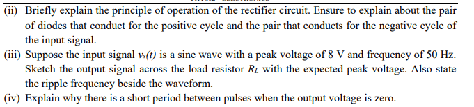
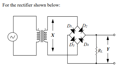
(ii) Briefly explain the principle of operation of the rectifier circuit. Ensure to explain about the pair of diodes that conduct for the positive cycle and the pair that conducts for the negative cycle of the input signal. (iii) Suppose the input signal vs(t) is a sine wave with a peak voltage of 8 V and frequency of 50 Hz. Sketch the output signal across the load resistor RL with the expected peak voltage. Also state the ripple frequency beside the waveform. (iv) Explain why there is a short period between pulses when the output voltage is zero.
(ii) Briefly explain the principle of operation of the rectifier circuit. Ensure to explain about the pair of diodes that conduct for the positive cycle and the pair that conducts for the negative cycle of the input signal. (iii) Suppose the input signal vs(t) is a sine wave with a peak voltage of 8 V and frequency of 50 Hz. Sketch the output signal across the load resistor RL with the expected peak voltage. Also state the ripple frequency beside the waveform. (iv) Explain why there is a short period between pulses when the output voltage is zero.

Electricity for Refrigeration, Heating, and Air Conditioning (MindTap Course List)
10th Edition
ISBN:9781337399128
Author:Russell E. Smith
Publisher:Russell E. Smith
Chapter12: Electronic Control Devices
Section: Chapter Questions
Problem 4RQ: What is the difference between a diode and rectifier?

Related questions
Question
Transcribed Image Text:(ii) Briefly explain the principle of operation of the rectifier circuit. Ensure to explain about the pair
of diodes that conduct for the positive cycle and the pair that conducts for the negative cycle of
the input signal.
(iii) Suppose the input signal vs(t) is a sine wave with a peak voltage of 8 V and frequency of 50 Hz.
Sketch the output signal across the load resistor R₂ with the expected peak voltage. Also state
the ripple frequency beside the waveform.
(iv) Explain why there is a short period between pulses when the output voltage is zero.
Transcribed Image Text:For the rectifier shown below:
2
elle
reeee
DI
D3
D₂
D4
RL
Expert Solution
This question has been solved!
Explore an expertly crafted, step-by-step solution for a thorough understanding of key concepts.

Step by step
Solved in 3 steps with 6 images

Follow-up Questions
Read through expert solutions to related follow-up questions below.
Follow-up Question

Transcribed Image Text:(iv) Explain why there is a short period between pulses when the output voltage is zero.
(v) Calculate Vdc and Vrms of the output voltage.
(vi) Explain how the ripple voltage from (ii) above can be eliminated. You may use circuit diagrams
to aid your answer.
(vii) Sketch the new output signal across the load resistor R, when the ripple voltage is eliminated.
Solution
Knowledge Booster


Learn more about
Need a deep-dive on the concept behind this application? Look no further. Learn more about this topic, electrical-engineering and related others by exploring similar questions and additional content below.Recommended textbooks for you
Electricity for Refrigeration, Heating, and Air C…
Mechanical Engineering
ISBN:
9781337399128
Author:
Russell E. Smith
Publisher:
Cengage Learning
Electricity for Refrigeration, Heating, and Air C…
Mechanical Engineering
ISBN:
9781337399128
Author:
Russell E. Smith
Publisher:
Cengage Learning