What is a rectifier? 2. How does a diode act as a rectifier? 3. What is the significance of PIV? What is the condition imposed on PIV? 4. What is meant by regulation? 5. What is meant by time constant? 6. What is meant by ripple factor?
What is a rectifier? 2. How does a diode act as a rectifier? 3. What is the significance of PIV? What is the condition imposed on PIV? 4. What is meant by regulation? 5. What is meant by time constant? 6. What is meant by ripple factor?

Introductory Circuit Analysis (13th Edition)
13th Edition
ISBN:9780133923605
Author:Robert L. Boylestad
Publisher:Robert L. Boylestad
Chapter1: Introduction
Section: Chapter Questions
Problem 1P: Visit your local library (at school or home) and describe the extent to which it provides literature...

Related questions
Question
100%
3.4 PRE-LABORATORY QUESTIONS
1. What is a rectifier?
2. How does a diode act as a rectifier?
3. What is the significance of PIV? What is the condition imposed on PIV?
4. What is meant by regulation?
5. What is meant by time constant?
6. What is meant by ripple factor?
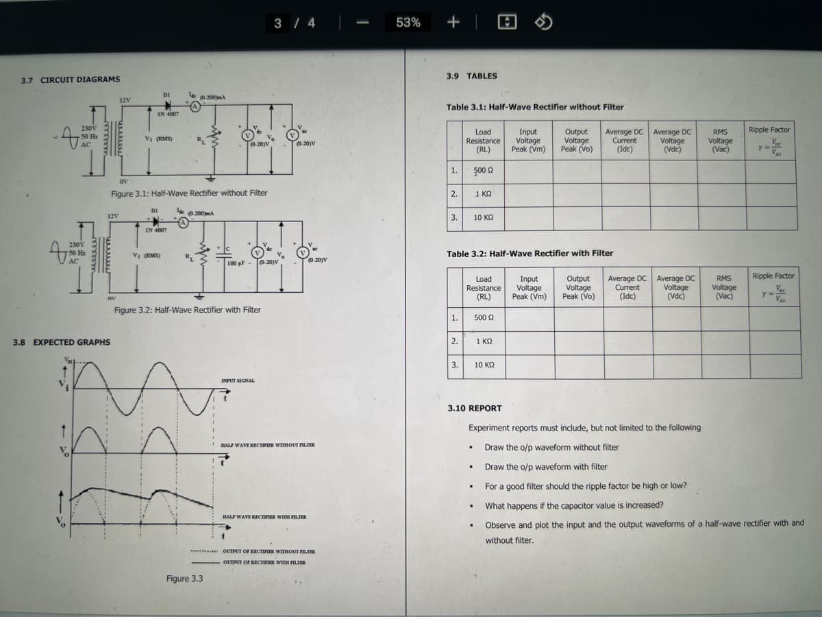
Transcribed Image Text:3.7 CIRCUIT DIAGRAMS
230V
50 H₂
AC
T
Vo
230V
50 H₂
AC
3.8 EXPECTED GRAPHS
12V
12V
nu
IN 4007
V₁ (RMS)
DI
DI
OV
Figure 3.1: Half-Wave Rectifier without Filter
IN 4007
Vi (RMS)
за
lac (0-200mA
lac
R₁
(0-200)m.A
R₁
+ C
I
Figure 3.3
(0-20)V
Figure 3.2: Half-Wave Rectifier with Filter
100 pF-
INPUT SIGNAL
t
3 / 4
(0-20)V
(0-20)V
HALF WAVE RECTIFIER WITHOUT FILTER
HALF WAVE RECTIFIER WITH FILTER
(0-20)V
***** OUTPUT OF RECTIFIER WITHOUT FILTER
OUTPUT OF RECTIFIER WITH FILTER
53%
+
3.9 TABLES
Table 3.1: Half-Wave Rectifier without Filter
1.
2.
3.
1.
2.
Load
Resistance
(RL)
500 Ω
1 ΚΩ
3.
Table 3.2: Half-Wave Rectifier with Filter
Load
Resistance
(RL)
.
.
10 ΚΩ
.
.
.
500 £2
1 KQ
Input
Output
Voltage Voltage
Peak (Vm) Peak (Vo)
10 ΚΩ
Input
Voltage
Peak (Vm)
Average DC Average DC
Current Voltage
(Idc)
(Vdc)
Output
Voltage
Peak (Vo)
Average DC
Current
(Idc)
Average DC
Voltage
(Vdc)
RMS
Voltage
(Vac)
RMS
Voltage
(Vac)
3.10 REPORT
Experiment reports must include, but not limited to the following
Draw the o/p waveform without filter
Draw the o/p waveform with filter
For a good filter should the ripple factor be high or low?
What happens if the capacitor value is increased?
Observe and plot the input and the output waveforms of a half-wave rectifier with and
without filter.
Ripple Factor
Vac
Vac
y =
Ripple Factor
Vac
Vac
Y =
Transcribed Image Text:3.1 AIM
EXPERIMENT 3
HALFWAVE RECTIFIERS WITH/WITHOUT FILTERS
Examine the input and output waveforms of a half wave rectifier with and without filters.
Calculate the ripple factor with load resistances of 500 2, 1 KQ, and 10 KQ, respectively. Calculate
ripple factor with a filter capacitor of 100 μF and the loads of 1 KQ, 2 KQ, and 10 K, respectively.
3.2 COMPONENTS & EQUIPMENT REQUIRED
1
2
DEVICES
a) AC Supply
b) Silicon Diodes
c) Capacitor
a) DC Voltmeter
b) AC Voltmeter
DC Ammeter
3
4 Cathode Ray Oscilloscope
5 Decade Resistance Box
6 Connecting wires
RANGE/RATING
9-0-9 V
1N4007
0.47 uF
0-20 V
0-20 V
0-50 mA
0-20 MHz
10 Ω-100 ΚΩ
5A
QUANTITY (in No.s)
1
1
1
1
1
1
1
1
12
3.3 THEORY
During positive half-cyde of the input voltage, the diode D1 is in forward bias and conducts
through the load resistor R1. Hence the current produces an output voltage across the load resistor
R1, which has the same shape as the +ve half-cycle of the input voltage.
Q Search
During the negative half-cycle of the input voltage, the diode is reverse biased and there is
no current through the circuit. L.e, the voltage across R1 is zero. The net result is that only the +ve
half-cycle of the input voltage appears across the load. The average value of the half-wave rectified
o/p voltage is the value measured on DC voltmeter.
For practical circuits, transformer coupling is usually provided for two reasons.
1. The voltage can be stepped up or stepped down as needed.
2. The AC source is electrically isolated from the rectifier. Thus, preventing shock hazards
in the secondary circuit.
3.4 PRE-LABORATORY QUESTIONS
1. What is a rectifier?
2. How does a diode act as a rectifier?
3. What is the significance of PIV? What is the condition imposed on PIV?
4. What is meant by regulation?
5. What is meant by time constant?
6. What is meant by ripple factor?
3.5 PRECAUTIONS
1. Ensure that the polarities of the power supply and the meters as per the circuit diagram.
2. Keep the input voltage knob of the regulated power supply in minimum position both when
switching ON or switching OFF the power supply.
3. No loose contacts at the junctions.
4. Ensure that the ratings of the meters are as per the circuit design for precision.
3.6 PROCEDURE
Half-Wave Rectifier without Filter
1. Connect the circuit as shown in Figure 3.1
2. Adjust the load resistance, RL to 500 2, and note down the readings of input and output
voltages through oscilloscope.
3. Note the readings of DC current, DC voltage and AC voltage.
4. Change the load resistance RL to 1 KQ and repeat the above procedure.
5. Change the load resistance RL to 10 K2 and repeat the above procedure.
6. Note down the values in Table 3.1
Half-Wave Rectifier with Filter
1. Connect the circuit as shown in Figure 3.2.
2. Repeat the procedure shown above.
3. Note down the values in Table 3.2.
DELL
W
R
Expert Solution
This question has been solved!
Explore an expertly crafted, step-by-step solution for a thorough understanding of key concepts.

Step by step
Solved in 3 steps with 2 images

Knowledge Booster


Learn more about
Need a deep-dive on the concept behind this application? Look no further. Learn more about this topic, electrical-engineering and related others by exploring similar questions and additional content below.Recommended textbooks for you
Introductory Circuit Analysis (13th Edition)
Electrical Engineering
ISBN:
9780133923605
Author:
Robert L. Boylestad
Publisher:
PEARSON

Delmar's Standard Textbook Of Electricity
Electrical Engineering
ISBN:
9781337900348
Author:
Stephen L. Herman
Publisher:
Cengage Learning

Programmable Logic Controllers
Electrical Engineering
ISBN:
9780073373843
Author:
Frank D. Petruzella
Publisher:
McGraw-Hill Education
Introductory Circuit Analysis (13th Edition)
Electrical Engineering
ISBN:
9780133923605
Author:
Robert L. Boylestad
Publisher:
PEARSON
Delmar's Standard Textbook Of Electricity
Electrical Engineering
ISBN:
9781337900348
Author:
Stephen L. Herman
Publisher:
Cengage Learning
Programmable Logic Controllers
Electrical Engineering
ISBN:
9780073373843
Author:
Frank D. Petruzella
Publisher:
McGraw-Hill Education

Fundamentals of Electric Circuits
Electrical Engineering
ISBN:
9780078028229
Author:
Charles K Alexander, Matthew Sadiku
Publisher:
McGraw-Hill Education

Electric Circuits. (11th Edition)
Electrical Engineering
ISBN:
9780134746968
Author:
James W. Nilsson, Susan Riedel
Publisher:
PEARSON

Engineering Electromagnetics
Electrical Engineering
ISBN:
9780078028151
Author:
Hayt, William H. (william Hart), Jr, BUCK, John A.
Publisher:
Mcgraw-hill Education,