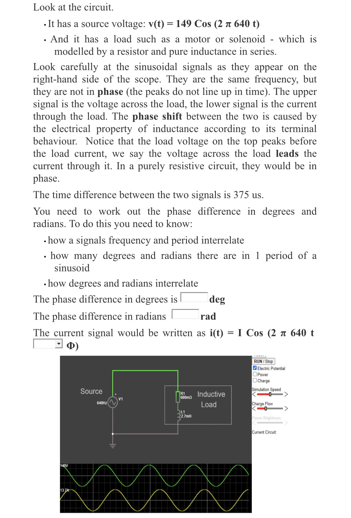
Look at the circuit. • It has a source voltage: v(t) = 149 Cos (2 t 640 t) · And it has a load such as a motor or solenoid - which is modelled by a resistor and pure inductance in series. Look carefully at the sinusoidal signals as they appear on the right-hand side of the scope. They are the same frequency, but they are not in phase (the peaks do not line up in time). The upper signal is the voltage across the load, the lower signal is the current through the load. The phase shift between the two is caused by the electrical property of inductance according to its terminal behaviour. Notice that the load voltage on the top peaks before the load current, we say the voltage across the load leads the current through it. In a purely resistive circuit, they would be in phase. The time difference between the two signals is 375 us. You need to work out the phase difference in degrees and radians. To do this you need to know: • how a signals frequency and period interrelate • how many degrees and radians there are in 1 period of a sinusoid • how degrees and radians interrelate The phase difference in degrees is deg The phase difference in radians rad The current signal would be written as i(t) I Cos (2 n 640 t Ф) RUN / Stop Electric Potential OPower OCharge Source Simulation Speed R1 680mQ Inductive V1 640HZ Load Charge Flow SL1 2.7mH Power Brightness Current Circuit: 149V 13.7A
Look at the circuit. • It has a source voltage: v(t) = 149 Cos (2 t 640 t) · And it has a load such as a motor or solenoid - which is modelled by a resistor and pure inductance in series. Look carefully at the sinusoidal signals as they appear on the right-hand side of the scope. They are the same frequency, but they are not in phase (the peaks do not line up in time). The upper signal is the voltage across the load, the lower signal is the current through the load. The phase shift between the two is caused by the electrical property of inductance according to its terminal behaviour. Notice that the load voltage on the top peaks before the load current, we say the voltage across the load leads the current through it. In a purely resistive circuit, they would be in phase. The time difference between the two signals is 375 us. You need to work out the phase difference in degrees and radians. To do this you need to know: • how a signals frequency and period interrelate • how many degrees and radians there are in 1 period of a sinusoid • how degrees and radians interrelate The phase difference in degrees is deg The phase difference in radians rad The current signal would be written as i(t) I Cos (2 n 640 t Ф) RUN / Stop Electric Potential OPower OCharge Source Simulation Speed R1 680mQ Inductive V1 640HZ Load Charge Flow SL1 2.7mH Power Brightness Current Circuit: 149V 13.7A

Introductory Circuit Analysis (13th Edition)
13th Edition
ISBN:9780133923605
Author:Robert L. Boylestad
Publisher:Robert L. Boylestad
Chapter1: Introduction
Section: Chapter Questions
Problem 1P: Visit your local library (at school or home) and describe the extent to which it provides literature...

Related questions
Question
Transcribed Image Text:Look at the circuit.
• It has a source voltage: v(t) = 149 Cos (2 n 640 t)
· And it has a load such as a motor or solenoid - which is
modelled by a resistor and pure inductance in series.
Look carefully at the sinusoidal signals as they appear on the
right-hand side of the scope. They are the same frequency, but
they are not in phase (the peaks do not line up in time). The upper
signal is the voltage across the load, the lower signal is the current
through the load. The phase shift between the two is caused by
the electrical property of inductance according to its terminal
behaviour. Notice that the load voltage on the top peaks before
the load current, we say the voltage across the load leads the
current through it. In a purely resistive circuit, they would be in
phase.
The time difference between the two signals is 375 us.
You need to work out the phase difference in degrees and
radians. To do this you need to know:
• how a signals frequency and period interrelate
· how many degrees and radians there are in 1 period of a
sinusoid
• how degrees and radians interrelate
The phase difference in degrees is
deg
The phase difference in radians
rad
The current signal would be written as i(t)
I Cos (2 n 640 t
%D
Ф)
RUN / Stop
Electric Potential
OPower
OCharge
Source
Simulation Speed
R1
680m2
Inductive
V1
640HZ
Load
Charge Flow
SL1
2.7mH
Power Brightness
Current Circuit:
149V
13.7A
Expert Solution
This question has been solved!
Explore an expertly crafted, step-by-step solution for a thorough understanding of key concepts.

Step by step
Solved in 3 steps with 2 images

Knowledge Booster


Learn more about
Need a deep-dive on the concept behind this application? Look no further. Learn more about this topic, electrical-engineering and related others by exploring similar questions and additional content below.Recommended textbooks for you
Introductory Circuit Analysis (13th Edition)
Electrical Engineering
ISBN:
9780133923605
Author:
Robert L. Boylestad
Publisher:
PEARSON

Delmar's Standard Textbook Of Electricity
Electrical Engineering
ISBN:
9781337900348
Author:
Stephen L. Herman
Publisher:
Cengage Learning

Programmable Logic Controllers
Electrical Engineering
ISBN:
9780073373843
Author:
Frank D. Petruzella
Publisher:
McGraw-Hill Education
Introductory Circuit Analysis (13th Edition)
Electrical Engineering
ISBN:
9780133923605
Author:
Robert L. Boylestad
Publisher:
PEARSON
Delmar's Standard Textbook Of Electricity
Electrical Engineering
ISBN:
9781337900348
Author:
Stephen L. Herman
Publisher:
Cengage Learning
Programmable Logic Controllers
Electrical Engineering
ISBN:
9780073373843
Author:
Frank D. Petruzella
Publisher:
McGraw-Hill Education

Fundamentals of Electric Circuits
Electrical Engineering
ISBN:
9780078028229
Author:
Charles K Alexander, Matthew Sadiku
Publisher:
McGraw-Hill Education

Electric Circuits. (11th Edition)
Electrical Engineering
ISBN:
9780134746968
Author:
James W. Nilsson, Susan Riedel
Publisher:
PEARSON

Engineering Electromagnetics
Electrical Engineering
ISBN:
9780078028151
Author:
Hayt, William H. (william Hart), Jr, BUCK, John A.
Publisher:
Mcgraw-hill Education,