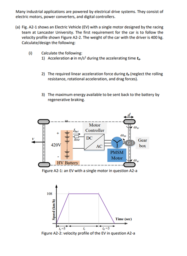
Many industrial applications are powered by electrical drive systems. They consist of electric motors, power converters, and digital controllers. (a) Fig. A2-1 shows an Electric Vehicle (EV) with a single motor designed by the racing team at Lancaster University. The first requirement for the car is to follow the velocity profile shown Figure A2-2. The weight of the car with the driver is 400 kg. Calculate/design the following: (0) Calculate the following: 1) Acceleration a in m/s² during the accelerating time to. 2) The required linear acceleration force during to (neglect the rolling resistance, rotational acceleration, and drag forces). 3) The maximum energy available to be sent back to the battery by regenerative braking.
Many industrial applications are powered by electrical drive systems. They consist of electric motors, power converters, and digital controllers. (a) Fig. A2-1 shows an Electric Vehicle (EV) with a single motor designed by the racing team at Lancaster University. The first requirement for the car is to follow the velocity profile shown Figure A2-2. The weight of the car with the driver is 400 kg. Calculate/design the following: (0) Calculate the following: 1) Acceleration a in m/s² during the accelerating time to. 2) The required linear acceleration force during to (neglect the rolling resistance, rotational acceleration, and drag forces). 3) The maximum energy available to be sent back to the battery by regenerative braking.

Elements Of Electromagnetics
7th Edition
ISBN:9780190698614
Author:Sadiku, Matthew N. O.
Publisher:Sadiku, Matthew N. O.
ChapterMA: Math Assessment
Section: Chapter Questions
Problem 1.1MA

Related questions
Question
ai the first 3 are a part
![Power [kW]
100
90
80
70
60
50
40
30
20
10
(ii) Figure A2-3 shows the torque and power of the employed EMRAX 208
Permanent magnet synchronous motor (PMSM). The team have a variable
gear box with a variable value for G between 1:1 to 1:6. They have three sets
of tyres as d; = 40 cm, d₂ = 50 cm, and d3 = 60 cm.
Design the drive train system by choosing a combination of d and the G so
the following requirements are satisfied:
(1) The motor torque does not exceed the peak value during acceleration
and;
(2) The motor speed does not exceed 6000 rpm which is recommended by
the motor controller's company.
Peak torque
Continuous torque
1000
2000
EMRAX 208HV LC
Peak power
Continuous power
3000
5000
6000
180
160
140
120
100
80
60
40
20
0
7000
Torque [N.m]
4000
Motor Speed [rpm]
Figure A2-3 Torque/speed curve for the motor in question A2-a
(iii) The old design of the car had G = 4.75 and d = 50 cm. It was noticed
during testing the car that the driver spends the majority of the race at a
speed in the range of 30 km/h to 50 km/h. Explain the effect of increasing G
to 6 on:
(1) The rotational speed of the motor during the majority of the race and
hence the available driving power.
(2) The frequency of the motor's voltage at the top speed of the car if the
EMRAX 208 motor has 20 poles (10 pole pairs).](/v2/_next/image?url=https%3A%2F%2Fcontent.bartleby.com%2Fqna-images%2Fquestion%2F98a2975c-b075-4e7f-95a3-3742d529c071%2F1b16a5e8-5b24-4cef-8ba4-061a6eb9e174%2Fyq3jl0p_processed.png&w=3840&q=75)
Transcribed Image Text:Power [kW]
100
90
80
70
60
50
40
30
20
10
(ii) Figure A2-3 shows the torque and power of the employed EMRAX 208
Permanent magnet synchronous motor (PMSM). The team have a variable
gear box with a variable value for G between 1:1 to 1:6. They have three sets
of tyres as d; = 40 cm, d₂ = 50 cm, and d3 = 60 cm.
Design the drive train system by choosing a combination of d and the G so
the following requirements are satisfied:
(1) The motor torque does not exceed the peak value during acceleration
and;
(2) The motor speed does not exceed 6000 rpm which is recommended by
the motor controller's company.
Peak torque
Continuous torque
1000
2000
EMRAX 208HV LC
Peak power
Continuous power
3000
5000
6000
180
160
140
120
100
80
60
40
20
0
7000
Torque [N.m]
4000
Motor Speed [rpm]
Figure A2-3 Torque/speed curve for the motor in question A2-a
(iii) The old design of the car had G = 4.75 and d = 50 cm. It was noticed
during testing the car that the driver spends the majority of the race at a
speed in the range of 30 km/h to 50 km/h. Explain the effect of increasing G
to 6 on:
(1) The rotational speed of the motor during the majority of the race and
hence the available driving power.
(2) The frequency of the motor's voltage at the top speed of the car if the
EMRAX 208 motor has 20 poles (10 pole pairs).
Transcribed Image Text:Many industrial applications are powered by electrical drive systems. They consist of
electric motors, power converters, and digital controllers.
(a) Fig. A2-1 shows an Electric Vehicle (EV) with a single motor designed by the racing
team at Lancaster University. The first requirement for the car is to follow the
velocity profile shown Figure A2-2. The weight of the car with the driver is 400 kg.
Calculate/design the following:
(1) Calculate the following:
1) Acceleration a in m/s² during the accelerating time to.
2) The required linear acceleration force during to (neglect the rolling
resistance, rotational acceleration, and drag forces).
3) The maximum energy available to be sent back to the battery by
regenerative braking.
‒‒‒‒‒
420V
108
HHK THE
| Speed (km/h)
Ibat
fuse
Motor
Controller
DC
AC
10
PMSM
Motor
---
HV Battery
Figure A2-1: an EV with a single motor in question A2-a
Ow
Time (sec)
@w
Gear
box
4
4-3
Figure A2-2: velocity profile of the EV in question A2-a
Expert Solution
This question has been solved!
Explore an expertly crafted, step-by-step solution for a thorough understanding of key concepts.

Step by step
Solved in 3 steps with 1 images

Knowledge Booster


Learn more about
Need a deep-dive on the concept behind this application? Look no further. Learn more about this topic, mechanical-engineering and related others by exploring similar questions and additional content below.Recommended textbooks for you
Elements Of Electromagnetics
Mechanical Engineering
ISBN:
9780190698614
Author:
Sadiku, Matthew N. O.
Publisher:
Oxford University Press

Mechanics of Materials (10th Edition)
Mechanical Engineering
ISBN:
9780134319650
Author:
Russell C. Hibbeler
Publisher:
PEARSON

Thermodynamics: An Engineering Approach
Mechanical Engineering
ISBN:
9781259822674
Author:
Yunus A. Cengel Dr., Michael A. Boles
Publisher:
McGraw-Hill Education
Elements Of Electromagnetics
Mechanical Engineering
ISBN:
9780190698614
Author:
Sadiku, Matthew N. O.
Publisher:
Oxford University Press
Mechanics of Materials (10th Edition)
Mechanical Engineering
ISBN:
9780134319650
Author:
Russell C. Hibbeler
Publisher:
PEARSON
Thermodynamics: An Engineering Approach
Mechanical Engineering
ISBN:
9781259822674
Author:
Yunus A. Cengel Dr., Michael A. Boles
Publisher:
McGraw-Hill Education

Control Systems Engineering
Mechanical Engineering
ISBN:
9781118170519
Author:
Norman S. Nise
Publisher:
WILEY

Mechanics of Materials (MindTap Course List)
Mechanical Engineering
ISBN:
9781337093347
Author:
Barry J. Goodno, James M. Gere
Publisher:
Cengage Learning

Engineering Mechanics: Statics
Mechanical Engineering
ISBN:
9781118807330
Author:
James L. Meriam, L. G. Kraige, J. N. Bolton
Publisher:
WILEY