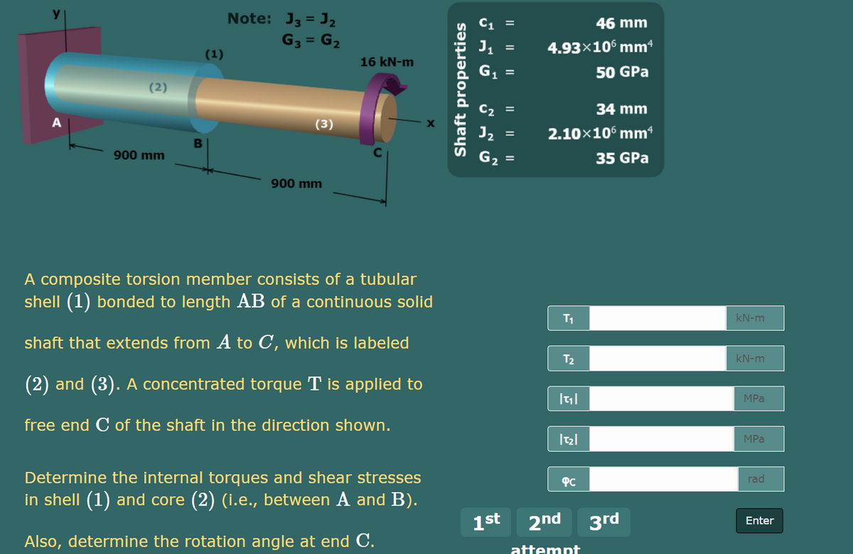
Note: J3 = J2 46 mm G3 = G2 4.93×10 mm (1) 16 kN-m 50 GPa (2) 34 mm %3D (3) 2.10x106 mm 900 mm 35 GPa %3D 900 mm A composite torsion member consists of a tubular shell (1) bonded to length AB of a continuous solid T1 kN-m shaft that extends from A to C, which is labeled T2 kN-m (2) and (3). A concentrated torque T is applied to MPa free end C of the shaft in the direction shown. MPa Determine the internal torques and shear stresses PC rad in shell (1) and core (2) (i.e., between A and B). 1st 2nd 3rd Enter Also, determine the rotation angle at end C. attemnt Shaft properties
Note: J3 = J2 46 mm G3 = G2 4.93×10 mm (1) 16 kN-m 50 GPa (2) 34 mm %3D (3) 2.10x106 mm 900 mm 35 GPa %3D 900 mm A composite torsion member consists of a tubular shell (1) bonded to length AB of a continuous solid T1 kN-m shaft that extends from A to C, which is labeled T2 kN-m (2) and (3). A concentrated torque T is applied to MPa free end C of the shaft in the direction shown. MPa Determine the internal torques and shear stresses PC rad in shell (1) and core (2) (i.e., between A and B). 1st 2nd 3rd Enter Also, determine the rotation angle at end C. attemnt Shaft properties

Mechanics of Materials (MindTap Course List)
9th Edition
ISBN:9781337093347
Author:Barry J. Goodno, James M. Gere
Publisher:Barry J. Goodno, James M. Gere
Chapter5: Stresses In Beams (basic Topics)
Section: Chapter Questions
Problem 5.9.5P: A sign for an automobile service station is supported by two aluminum poles of hollow circular cross...

Related questions

Question
Transcribed Image Text:Note: J3 = J2
46 mm
G3 = G2
4.93×10° mm
(1)
16 kN-m
50 GPa
(2)
C2 =
34 mm
(3)
J2
2.10x10° mm*
B
900 mm
35 GPa
900 mm
A composite torsion member consists of a tubular
shell (1) bonded to length AB of a continuous solid
T1
kN-m
shaft that extends from A to C, which is labeled
T2
kN-m
(2) and (3). A concentrated torque T is applied to
MPa
free end C of the shaft in the direction shown.
MPa
Determine the internal torques and shear stresses
PC
rad
in shell (1) and core (2) (i.e., between A and B).
1st 2nd 3rd
Enter
Also, determine the rotation angle at end C.
attempt
II || ||
I| || ||
Shaft properties
Expert Solution
This question has been solved!
Explore an expertly crafted, step-by-step solution for a thorough understanding of key concepts.

Step by step
Solved in 2 steps with 2 images

Knowledge Booster


Learn more about
Need a deep-dive on the concept behind this application? Look no further. Learn more about this topic, mechanical-engineering and related others by exploring similar questions and additional content below.Recommended textbooks for you
Mechanics of Materials (MindTap Course List)
Mechanical Engineering
ISBN:
9781337093347
Author:
Barry J. Goodno, James M. Gere
Publisher:
Cengage Learning
Mechanics of Materials (MindTap Course List)
Mechanical Engineering
ISBN:
9781337093347
Author:
Barry J. Goodno, James M. Gere
Publisher:
Cengage Learning