O Consider the table given below in which A, B, C, and D are input variables. F is the output variable. i. ii. Construct a Karnaugh map for the output variable Use AND, OR, and NOT gates to draw the logic circuit of the minimum SOP expression of the output variable. A B D F
O Consider the table given below in which A, B, C, and D are input variables. F is the output variable. i. ii. Construct a Karnaugh map for the output variable Use AND, OR, and NOT gates to draw the logic circuit of the minimum SOP expression of the output variable. A B D F

Chapter22: Sequence Control
Section: Chapter Questions
Problem 6SQ: Draw a symbol for a solid-state logic element AND.

Related questions

Question
just trying to do past exam questions but I'm struggling, need help to understand this question.
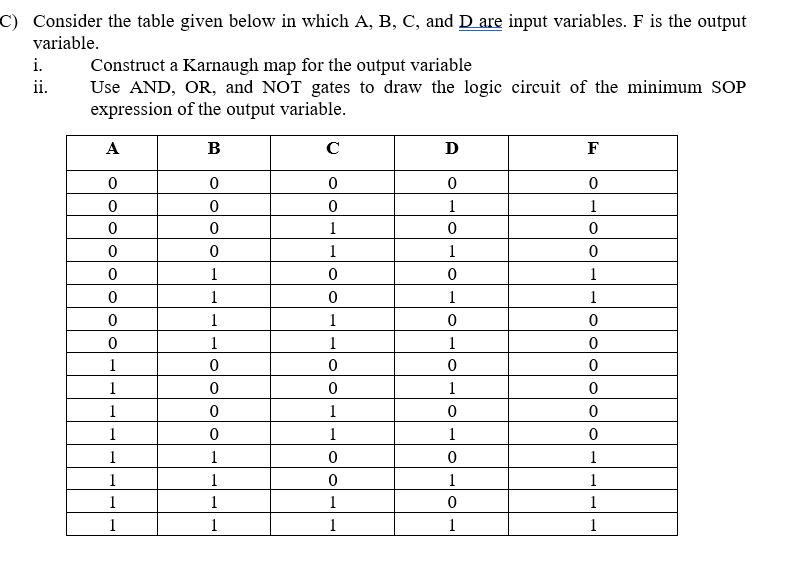
Transcribed Image Text:C) Consider the table given below in which A, B, C, and D are input variables. F is the output
variable.
i.
Construct a Karnaugh map for the output variable
Use AND, OR, and NOT gates to draw the logic circuit of the minimum SOP
expression of the output variable.
ii.
А
B
C
D
F
ㅇ
1
1
1
1
1
1
1
1
1
1
1
1
1
1
1
1
1
1
1
1
1
1
1
1
1
1
1
1
1
1
1
1
1
1
1
1
1
1
1
Expert Solution
This question has been solved!
Explore an expertly crafted, step-by-step solution for a thorough understanding of key concepts.

This is a popular solution!

Trending now
This is a popular solution!

Step by step
Solved in 2 steps with 1 images

Knowledge Booster


Learn more about
Need a deep-dive on the concept behind this application? Look no further. Learn more about this topic, electrical-engineering and related others by exploring similar questions and additional content below.Recommended textbooks for you