OBJECTIVE The study of nodal analysis is the objective of this exercise, specifically its usage in multi-source DC circuits. Its application to finding circuit currents and voltages will be investigated. THEORY OVERVIEW Multi-source DC circuits may be analyzed using a node voltage technique. The process involves identifying all of the circuit nodes, a node being a point where various branch currents combine. A reference node, usually ground, is included. Kirchhoff's Current Law is then applied to each node. Consequently a set of simultaneous equations are created with an unknown voltage for each node with the exception of the reference. In other words, a circuit with a total of five nodes including the reference will yield four unknown node voltages and four equations. Once the node voltages are determined, various branch currents and component voltages may be derived.
OBJECTIVE The study of nodal analysis is the objective of this exercise, specifically its usage in multi-source DC circuits. Its application to finding circuit currents and voltages will be investigated. THEORY OVERVIEW Multi-source DC circuits may be analyzed using a node voltage technique. The process involves identifying all of the circuit nodes, a node being a point where various branch currents combine. A reference node, usually ground, is included. Kirchhoff's Current Law is then applied to each node. Consequently a set of simultaneous equations are created with an unknown voltage for each node with the exception of the reference. In other words, a circuit with a total of five nodes including the reference will yield four unknown node voltages and four equations. Once the node voltages are determined, various branch currents and component voltages may be derived.

Introductory Circuit Analysis (13th Edition)
13th Edition
ISBN:9780133923605
Author:Robert L. Boylestad
Publisher:Robert L. Boylestad
Chapter1: Introduction
Section: Chapter Questions
Problem 1P: Visit your local library (at school or home) and describe the extent to which it provides literature...

Related questions
Question
USE MULTISM
Transcribed Image Text:OBJECTIVE
The study of nodal analysis is the objective of this exercise, specifically its usage in multi-source
DC circuits. Its application to finding circuit currents and voltages will be investigated.
THEORY OVERVIEW
Multi-source DC circuits may be analyzed using a node voltage technique. The process involves
identifying all of the circuit nodes, a node being a point where various branch currents combine.
A reference node, usually ground, is included. Kirchhoff's Current Law is then applied to each
node. Consequently a set of simultaneous equations are created with an unknown voltage for
each node with the exception of the reference. In other words, a circuit with a total of five nodes
including the reference will yield four unknown node voltages and four equations. Once the
node voltages are determined, various branch currents and component voltages may be
derived.
EQUIPMENT
(1) Adjustable DC Power Supply
(1) Digital Multimeter
(1) 4.7 k2
(1) 6.8 k2
(1) 10 ka
(1) 22 k2
(1) 33 ka
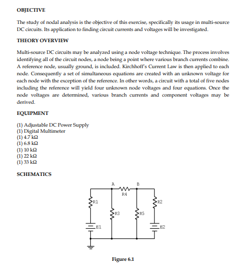
SCHEMATICS
B
R4
R1
R2
R3
R5
EB1
E2
Figure 6.1
Transcribed Image Text:PROCEDURE
1. Consider the dual supply circuit of Figure 6.1 using E1 = 6 volts, E2 = 12 volts, R1 = 4.7
k, R2 = 6.8 k, R3 = 10 k, R4 = 22 k and R5 = 33 k. Applying nodal analysis to this circuit
yields two equations with two unknowns, namely node voltages A and B. Again, once
these potentials are found, any other circuit current or voltage may be determined by
applying Ohm's Law and/or KVL and KCL.
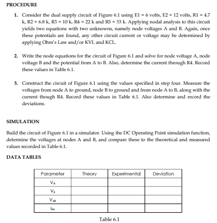
2. Write the node equations for the circuit of Figure 6.1 and solve for node voltage A, node
voltage B and the potential from A to B. Also, determine the current through R4. Record
these values in Table 6.1.
3. Construct the circuit of Figure 6.1 using the values specified in step four. Measure the
voltages from node A to ground, node B to ground and from node A to B, along with the
current though R4. Record these values in Table 6.1. Also determine and record the
deviations.
SIMULATION
Build the circuit of Figure 6.1 in a simulator. Using the DC Operating Point simulation function,
determine the voltages at nodes A and B, and compare these to the theoretical and measured
values recorded in Table 6.1.
DATA TABLES
Parameter
Theory
Experimental
Deviation
VA
Vs
V
Table 6.1
Expert Solution
This question has been solved!
Explore an expertly crafted, step-by-step solution for a thorough understanding of key concepts.

This is a popular solution!

Trending now
This is a popular solution!

Step by step
Solved in 2 steps with 1 images

Knowledge Booster


Learn more about
Need a deep-dive on the concept behind this application? Look no further. Learn more about this topic, electrical-engineering and related others by exploring similar questions and additional content below.Recommended textbooks for you
Introductory Circuit Analysis (13th Edition)
Electrical Engineering
ISBN:
9780133923605
Author:
Robert L. Boylestad
Publisher:
PEARSON

Delmar's Standard Textbook Of Electricity
Electrical Engineering
ISBN:
9781337900348
Author:
Stephen L. Herman
Publisher:
Cengage Learning

Programmable Logic Controllers
Electrical Engineering
ISBN:
9780073373843
Author:
Frank D. Petruzella
Publisher:
McGraw-Hill Education
Introductory Circuit Analysis (13th Edition)
Electrical Engineering
ISBN:
9780133923605
Author:
Robert L. Boylestad
Publisher:
PEARSON
Delmar's Standard Textbook Of Electricity
Electrical Engineering
ISBN:
9781337900348
Author:
Stephen L. Herman
Publisher:
Cengage Learning
Programmable Logic Controllers
Electrical Engineering
ISBN:
9780073373843
Author:
Frank D. Petruzella
Publisher:
McGraw-Hill Education

Fundamentals of Electric Circuits
Electrical Engineering
ISBN:
9780078028229
Author:
Charles K Alexander, Matthew Sadiku
Publisher:
McGraw-Hill Education

Electric Circuits. (11th Edition)
Electrical Engineering
ISBN:
9780134746968
Author:
James W. Nilsson, Susan Riedel
Publisher:
PEARSON

Engineering Electromagnetics
Electrical Engineering
ISBN:
9780078028151
Author:
Hayt, William H. (william Hart), Jr, BUCK, John A.
Publisher:
Mcgraw-hill Education,