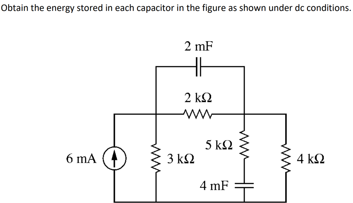
Obtain the energy stored in each capacitor in the figure as shown under dc conditions. 2 mF 2 k2 5 k2 6 mA (4 3 k2 4 k2 4 mF ww


Q: Consider the object shown in Fig. 1(b). Calculate: i. The length of CD ii. The surface area ABCD ii....
A: Use differential length, differential surface and differential volume formula in cylindrical coordi...
Q: 2. If A = 2a, + 6a, – 3a, and B = - 3n, – 4a, - Sa,, find: (a) a unit vector in the direction of A -...
A:
Q: Ex. 1632. A 120VÁC_RMS, 6 0Hz line is connected to an SCR with a firing angle of 93 degrees. output?...
A:
Q: Q.2 Let x[n], v[n] be defined as follows: [n] = 8[n - 1] - 8[n + 1] v/n] = ad[n] + b[n – 1]+ co[n-2]...
A: The impulse signal δn is an identity function in the convolution operation which means that fn-a*δn-...
Q: 400V 50HZ system connected to a full controlled rectifier through a delta to star transformer. The r...
A:
Q: 4. Find the transfer function Vo(s)/V(t), for each network shown in figure 4. 2/ Vo(s)
A:
Q: The SCR operation characteristic is plotted for a. Va vs Ig with Ia as a parameter b.
A: In this question we will write about SCR operational characteristics....
Q: Use Norton's theorem to determine the current I flowing in the 42 resistance shown in Figure 4 V 2V ...
A:
Q: A 30 kW, 300V d.c. shunt generator has armature and field resistances of 0.05 0 and 100 0 respective...
A: It is given that: V=300 VP=30 KWRa=0.05 ΩRsh=100 Ω
Q: (a) Calculate Vos and Ves in Figure 5 when In =8 mA. Assume that Rp= 860 2. Rs= 390Q RG = 10 M2 and ...
A: The given amplifier circuit is a self biased JFET and the required parameters can be obtained by usi...
Q: is Vs - 20 L - 30°V impedance Q.) the Voltage Source terminal a-b is In Figure below Connected load ...
A: In this question, Find the load impedance if load current Io is given. We know Z= V/I We are solvi...
Q: I need help sloving for I2 1100I2 - (3300)(10 + 3300I2)/4500 = - 10
A: To solve for I2 from the given equation
Q: Given the following circuit, solve for Vo. Must use mesh Analysis. 12 mA 6 ΚΩ ww 3 k. 6 mA 12 V $12 ...
A: This question belongs to circuit theory . It is based on the concept of mesh analysis . Mesh analysi...
Q: D Question 6 For the sine wave shown below determine the RMS voltage. The Horizontal scale "time bas...
A:
Q: Using A-Y conversion of source (don't use KVL), prove that the line current Ia in Figure 1(a) as 1 V...
A: THREE-PHASE CONNECTION A three-phase connection is nothing but the three single-phases displaced ...
Q: 2.) Apply the core concepts of Faraday's law to solve the following questions a) State Faraday's Law...
A: We have given the following problem
Q: For a single phase half wave rectifier feeding 10 ohms load with input supply voltage of (use your l...
A: Since you have posted the questions with multiple subpart so we are supposed to answer 3 subpart.
Q: Calculate the current / through each of the transistor Q2 and Qa in the circuit of Fig. +6 V Tcontro...
A: Current mirror circuit A transistor circuit that regulates the current through the load resistance. ...
Q: 2) A light sensitive switch needs a voltage of 0.45V to compare to the voltage coming from the light...
A:
Q: The transformation ratio therefore is: 200 2 20.6 20
A: Given : a step down transformer Primary side voltage = 4600 v And secondary side voltage = 230 v
Q: R, 10uF Emitter - follower CE amplifier i ka 10uF 4- 50 k2 2,-12 k2 R222 ka 2-4.6 ka 640 Z- 202
A: We are authorized to answer three subparts at a time since you have not mentioned which part you are...
Q: A shunt motor has lap-wound armature with 100 slots with 2 turns per coil. It is rotating at 100rpm....
A:
Q: Solve the new potential difference of two capacitors 4 microfarad and 7 microfarad are connected in ...
A:
Q: A compound DC motor with lap-wound armature is connected to a 132V source. Shunt field resistance is...
A: As per the guidelines given, We can only provide the solution of the first three questions in multi-...
Q: A 30 kW, 300V d.c. shunt generator has armature and field resistances of 0.05 0 and 100 N respective...
A: Here, we have given a problem related to dc shunt generator. We have to calculate the total develop...
Q: 2.26. Using only the Fourier transform of the unit im- pulse function and appropriate transform theo...
A:
Q: 2300V to 230V step down transforme ave the following resistances and induc Re' =0.093 ohm Re" = 0.00...
A:
Q: + Vi - - Vz + R, = 1.2 kn A R, = 2.2 kn 20 V V3 3.3 kn 10 V FIG. 14.1 (b) Using branch-current analy...
A:
Q: A 16 pole, 3Φ synchronous generator has a resultant air gap flux of 0.06 wb per pole. The flux is d...
A:
Q: | Ox0000805C Ox07 a) CMP R6, RO b) ORRS R1, R2, R1 R1 c) LDR R1, [RS, #8]! R1 d) MOV PC, LR NZ Flags...
A: The given table of resister values is shown below,
Q: 5. The circuit shown in Fig. Pl.5 is a combination of devices, with the voltages and currents Vy as ...
A: This question belongs to circuit theory . It is about differentiate between Power absorbed and Power...
Q: Find the Total Inductance in the Circuit. 2 mH 4 mH 5 mH SA 2 mH 6 mH LT 12 mH 4 mH QB 2 mH 3 mH 2 m...
A: Conductance gets added up in series like resistance and similarly reduces to L1*L2/(L1+L2) like resi...
Q: 12.43 Find f(t) for each of the following functions. 135 a) F(s) : s(s + 3)*" 10(s + 2)2 b) (s) (2 +...
A: a) F(s) = 135s (s+3)2 There are no zeros Poles are s = 0 and s= -3 (its a double pole) ...
Q: 4. Determine the effective resistance of a practical 3H inductor that has 6002 of impedance in a 20H...
A:
Q: Given an input sinewave of 20Vpk-pk with its axis at the origin. If the axis is raised to 10V, at wh...
A: Given an input sinewave of 20Vpk-pk with its axis at the origin. If the axis is raised to 10V, at wh...
Q: 12MA 32-2k2 3mA IK-2 Z1.5Ke 1-sk
A: 6. The given circuit diagram is shown below:
Q: Q4: a) Determine the output voltage for the circuit of Fig.4. Where the frequency is 5 KHz and e = w...
A:
Q: Question 3 IN4747A zener diode is used in the regulator circuit shown in Figure 2. If the Zener diod...
A: a) With the given data sheet of 1N4730A, Voltage regulator Circuit is Now the reverse VI characte...
Q: Given the inputs A,B,C and D please make a truth table for the outputs at points F,G and H (а) U8 A:...
A: Since you have posted the multiple questions so we are supposed to answer the 1st question. a)
Q: Design a gate-level implementation for the following expressions using the specified gate types. Use...
A:
Q: full load regulation
A: Voltage regulation- The ratio of the change in the voltage (i.e. rise in voltage) when full-loa...
Q: A coil with 200 turns is linked with the flux given by o(t)=2tcos(6t + 34° )Wb. Determine the magnit...
A: In this question , coil is given with flux associated with it...We have to find out voltage induced ...
Q: . Implement the following circuit using components for an and gate, an or gate, and an inverter. You...
A: Given the following the circuit as shown below: We need to write the code for circuit implementatio...
Q: A single phase AC motor draws 4.5 A from the 220 V, 50 Hz network. The active power drawn by the mot...
A: 1-ϕ AC motor draws current=4.5AI=4.5AV=220VP=720WSolving by the formula-P=VIcosϕPutting the values g...
Q: A compound DC motor with lap-wound armature is connected to a 132V source. Shunt field resistance is...
A: The solution is given below
Q: For given figure below, find the equivalent resistance between points a and b if R1 = 5.8 Q, R2= 7.7...
A: Given
Q: Find the inverse laplace transform of F(s) = 6s/(s^2 + 25) + 3/(s^2 + 25) *
A: This question belongs to signal and system . It is about inverse Laplace transform of the function ....
Q: 3. The vector RA, extends from A(1,2,3) to B. If the length of R is 10 units and its direction is gi...
A: From given length and direction of vector Rab find the fictor Rab. Write the vector Rab interms of c...
Q: A 4600 to 230 Volts, 60 Hz step down
A:
Q: 1. At +20V, what is the output Clamper Circuit for numbers 1 to 4. voltage? O 48V -28V Vin Vout OV B...
A: Brief description: Clamper circuits are analog discrete circuits which are made up of resistor, capa...

Step by step
Solved in 3 steps with 2 images


- Three capacitors having capacitance values of 20F,40F, and 50F are connected in parallel to a 60 - Hz power line. An ammeter indicates a circuit current of 8.6 amperes. How much current is flowing through the 40F capacitor?You are an electrician working in an industrial plant. You discover that the problem with a certain machine is a defective capacitor. The capacitor is connected to a 240-volt AC circuit. The information on the capacitor reveals that it has a capacitance value of 10 mF and a voltage rating of 240 VAC. The only 10-mF AC capacitor in the storeroom is marked with a voltage rating of 350 WVDC. Can this capacitor be used to replace the defective capacitor? Explain your answer.You are working in an industrial plant. You have been instructed to double the capacitance connected to a machine. The markings on the capacitor, however, are not visible. The capacitor is connected to 560 volts and an ammeter indicates a current of 6 amperes flowing to the capacitor. What size capacitor should be connected in parallel with the existing capacitor? What is the minimum AC voltage rating of the new capacitor? What is the minimum DC voltage rating of the new capacitor? What is the minimum KVAR size that can be used in this installation?
- Fill in all the missing values. Refer to the formulas that follow. Resistance Capacitance Time constant Total time 150 k 100 F 350 k 35 s 350 pF 10 s 0.05 F 1.2 M 0.47 F 12F 0.05 s 86 k 1.5 s 120 k 470 pF 250 nF 100 ms 8 F 150 s 100 k 150 ms 33 k 4 F =RCR=CC=R Totaltime=5What is the unit of measurement for the strength of a capacitor? microamp microtorque microfarad microwattAn AC circuit contains a 24 resistor, a 15.9-mH inductor, and a 13.3F capacitor connected in parallel. The circuit is connected to a 240-V, 400-Hz power supply. Find the following values. XL=XC=IR=AIL=AIC=AP=WVARsL=VARsC=IT=AVA=PF=%=
- Assume that the current flow through the resistor, IR, is 15 A; the current flow through the inductor, IL is 36 A; and the circuit has an apparent power of 10,803 VA. The frequency of the AC voltage is 60 Hz. ET ER EL IT IR15A IL36A Z R XL VA10,803 P VARSL PF LA postage stamp mica capacitor has the following color marks starting at the upper left dot: yellow, violet, brown, green, no color, and blue. What are the capacitance value, tolerance, and voltage rating of this capacitor?A capacitor uses air as a dielectric and has a capacitance of 3 F. A dielectric material is inserted between the plates without changing the spacing, and the capacitance becomes 15 F. What is the dielectric constant of this material?
- Inductive Circuits Fill in all the missing values. Refer to the following formulas: XL=2fLL=XL2ff=XL2L Inductance (H) Frequency (Hz) Inductive Reactance ( ) 1.2 60 0.085 213.628 1000 4712.389 0.65 600 3.6 678.584 25 411.459 0.5 60 0.85 6408.849 20 201.062 0.45 400 4.8 2412.743 1000 40.841Three capacitors having values of 2.2 F, 280 F, and 470 pF are connected in parallel. What is the total capacitance?You find that a 25-F capacitor connected to 480 VAC is defective. The storeroom has no capacitors with a 480-VAC rating. However, you find two capacitors rated at 50 F and 370 VAC. Can these two capacitors be connected in such a manner that they can replace the defective capacitor? If yes, explain how they are connected and why the capacitors will not be damaged by the lower voltage rating. If no, explain why they cannot be used without damaging the capacitor.
