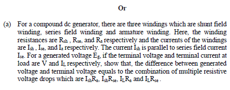
Or (a) For a compound de generator, there are three windings which are shunt field winding, series field winding and amature winding. Here, the winding resistances are Rah , Ra, and Ra respectively and the currents of the windings are Ia , Ia, and Ia respectively. The current Ím is parallel to series field curent Ise. For a generated voltage Eg, if the terminal voltage and terminal current at load are V and IL respectively, show that, the difference between generated voltage and terminal voltage equals to the combination of multiple resistive voltage drops which are IRa, IR2, IR, and IRe.
Q: A three-phase, 60 Hz synchronous generator in Fig. 1 delivers 0.9 per-unit real power at 1.08 per…
A: a) Total reactance of the circuit is calculated as follows: Xeq=0.1+0.2×0.30.2+0.3=0.1+0.060.50.22…
Q: Which of the following is true in the phasor diagrams drawn according to the ohmic, inductive and…
A: According to question we have to discuss Which of the following is true in the phasor diagrams drawn…
Q: The yearly duration curve of a certain plant may be considered as a straight line from 100 MW to 40…
A: Maximum demand = 100 x 103kwMinimum demand = 40 x 103 kwInstalled capacity = 40 x 103 kw of 2 No⇒30…
Q: Q.6: A (500 MW) synchronous generator is delivering (100 Mw) to infinite bus through the unit…
A:
Q: 18. The external characteristic of a shunt generator can be obtained directly from its -…
A: 18..>> The external characteristic of shunt generator can be obtained by directly from its…
Q: current, load power, and power loss under this condition? 16. A 228-volt constant-potential…
A:
Q: A simple power system is shown in this Fig. The generator (480 V, 10 kVA) is connected to an ideal…
A:
Q: ) Name the component in the generator which produces unidirectional current. i)Draw the experimental…
A: The shunt generator delivers 160A (IL) at a terminal voltage of 230V (Vt). The shunt field current…
Q: (c)Derive EMF Equation of the DC generator
A: Let ∅ = flux per poleZ = total armature conductorA = number of parallel pathP = number of polesN =…
Q: B- 1- Draw phasor diagram of an alternator works at lagging p.f.? Mention the alternator EMF…
A:
Q: A long-shunt compound generator delivers a load current of 50A at 500V and has armature, series…
A:
Q: A simple power system is shown in this Fig. The generator (480 V, 10 kVA) is connected to an ideal…
A:
Q: PA FAB DA = 2000 MW DB = 1000 MW Figure P6.2 Two-bus power system for Problems 6.2, 6.3, 6.4, 6.10…
A: According to guidelines we need to solve only first three subparts. According to the question,…
Q: Example: A30,5KVA,208V,60HZ,synchronous machine has negligible stator winding resistance and Xs =80…
A: Given information a three phase synchronous machine which is operated as a generator is, Rated…
Q: Figure Q2(a): Synchronous Generator (i) Name the type of synchronous generator as shown in Figure…
A: A synchronus generator is a synchronus machine which converts mechanical power into AC electric…
Q: A 6600V, 3-ph, Y-connected alternator has a synchronous impedance of (0.4+j6) ohm per phase.…
A:
Q: Q5) discuss the synchronous generator 1- principle operation 2- frequency 3- equivalent circuit
A:
Q: At the end of the 8 km overhead line given in the figure below, there are two distribution…
A: According to question: The currents 'I1' and 'I2' in the distribution transformer is calculated as
Q: 6.5 Consider the three-bus power system shown in Figure P6.5 The table below shows the data about…
A:
Q: A 2-pole, 50 Hz, 11 kV synchronous generator with a rating of 120 MW and 0.87 lagging power factor…
A: Question: A 2-pole, 50 Hz, 11 kV synchronous generator with a rating of 120 MW and 0.87 lagging…
Q: Which of the following is true for the phasor diagrams drawn according to the ohmic, inductive and…
A: For a synchronous motor, In normal excitation condition, synchronous motor draws sufficient amount…
Q: 4.2.Two generators, G1 and G2, have no-load frequencies of 61.5 Hz and 61.0 Hz, respectively. They…
A: In this question we need to find a system frequency and the power contribution of each generator…
Q: (a) | The cost curves of a three-generator system are given below: Q1 C1 = 350 + 7.20P + 0.0040P? C2…
A: As per the guidelines of Bartley we supposed to answer first three subpart only
Q: A shunt generator supplies a 25kW load at 235V through cables of resistance, R = 116mn. If the field…
A:
Q: Q2. The synchronous motor of Problem Q1 is supplied from a 575-V source through a feeder with a…
A: According to the question, calculate the magnitude and phase angle of the line-to-neutral generated…
Q: 6. For a series dc generator with Rs =12, R, = 3 2, and V, = 60 V that delivers 240 W to the load,…
A: Note :- as per guidelines only the first question can be solved, kindly re post the other questions…
Q: Using finite difference method, determine potential and magnitude of electric field at free nodes in…
A: The following is the answer :
Q: The fuel cost curve of two generator are given under C1 = 00+ 45 P +01 P;? C) = 2000 + 43 P + 0.003…
A:
Q: Explain the power flow diagram of a de generator. Q1/
A:
Q: - Comment on the possible industrial application of cumulatin compound generator types, series,…
A: Application of various DC Generator for the industrial applications. DC series generator,…
Q: A simple power system is shown in this Fig. The generator (480 V, 10 kVA) is connected to an ideal…
A: Given Data: KVA = 10 Voltage = 480 V Z=10 Ohm and angle =30 R=20 Ohm and X=60 Ohm
Q: (b) A salient pole synchronous generator with negligible resistance, has the following per unit…
A:
Q: 40) An induction machines dynamic performance can be described by space vector theory. The stator…
A: Hello. Since you have posted multiple questions and not specified which question needs to be solved,…
Q: An area of an interconnected 60-Hz power system has three turbine-generator units rated 200, 300,…
A: a) Given Sbasenew=100 MVA Calculating unit area frequency β=1R1punew+1R2punew+1R3punew…
Q: For minimum cost of power generation the generator limits are consider as inequality constraints…
A: for the economic power generation the value of the power generation by the generator should be…
Q: Generator manufacturers often use the term WR2, which is the weight in pounds of all the rotating…
A: The formula for the Kinetic energy is given as:
Q: Kust do l18 11.8 The synchronous generator in Figure 11.4 delivers 0.8 per-unit real power at 1.05…
A:
Q: A synchronous generator.connected to 1.0 per unit voltage infinite bus has 0.8 per unit reactance.…
A:
Q: The torque angle of synchronous machine operating from a constant voltage bus, is usually defined as…
A: The torque angle of synchronous machine operating from a constant voltage bus, is usually defined as…
Q: v) Define the term of degree of compounding in DC generators. What are the applications of different…
A: Degree of compounding is defined by the number of turns in series field winding and shunt field…
Q: Q3: A synchronous generator with peak generated voltage Vg which is connected to a lighting arrester…
A: 1) Peak value of the generated voltage of the synchronous generator= Vg RMS value of the generated…
Q: A long shunt generator delivers 25kW at 220V. The shunt, series and armature resistances are 50ohms,…
A:
Q: A 3-phase, Y connected, round rotor synchronous generator rated at 12KVA, 230V has a Synchronous…
A: i have explained in detail
Q: A network consisting of a set of generator and load buses is to be modeled with a DC power flow, for…
A: Given PTDF5,42-4 =-0.2609 LODF2-4,4-5 =-0.6087 Base case flow on line 4-5 is F04-5=13.6 MW Base case…
Q: Given two thermal generating units. For an accuracy of 1.8 MW, and two iterations were performed…
A: First iteration results P1k =180.5 MW P2k =160.5 MW second iteration results P2k+1 =162.8 MW P1k+1…
Q: A power plant comprises three turbine-generators rated 1000 MW, 800 MW and 600 MW respectively. The…
A: Note: We are authorized to answer three subparts at a time since you have not mentioned which part…
Q: rpm when operating at its rated load. The equivalent circuit has the following per-phase :parameters…
A:
Q: A 3 phase, star-connected, cylindrical rotor, 10 MVA, 11kV synchronous generator is supplying rated…
A: Given a synchronous generator with 10 MVA ,11 KV The terminal voltage and real power is constant…
Q: Discuss about generator modeling and drive the formula for the real and reactive power supply it .
A: Generator modeling - The simplest sophisticated modeling in a system stability tool are generator…
Step by step
Solved in 3 steps with 3 images
- Consider a three-phase generator rated 300MVA,23kV, supplying a system load of 240 MA and 0.9 power factor lagging at 230 kV through a 330MVA,23/230Y-kV step-up transformer with a leakage reactance of 0.11 per unit. (a) Neglecting the exciting current and choosing base values at the load of 100 MVL and 230 kV. Find the phasor currents IA,IB, and IC supplied to the load in per unit. (b) By choosing the load terminal voltage IA as reference, specify the proper base for the generator circuit and determine the generator voltage V as well as the phasor currents IA,IB, and IC, from the generator. (Note: Take into account the phase shift of the transformer.) (C) Find the generator terminal voltage in kV and the real power supplied by the generator in MW. (d) By omitting the transformer phase shift altogether, check to see whether you get the same magnitude of generator terminal voltage and real power delivered by the generator.The fuel-cost curves for two generators are given as follows: C1(P1)=600+18P1+0.04(P1)2C2(P2)=700+20P2+0.03(P2)2 Assuming the system is lossless, calculate the optimal dispatch values of P1 and P2 for a total load of 1000 MW, the incremental operating cost, and the total operating cost.Problem 1. to. In the problem shown, calculate the Load node regulation. Assume the generator maintains its generation voltage in terminals
- a) With the aid of a diagram and phasor diagram, explain the double-reactance concept for salient-pole alternators. b) 3-phase star-connected synchronous generator supplies a current of 10A having phase angle of 20° lagging 400V (phase voltage). Given the direct and quadrature axis reactances as 10ohms and 6.5ohms respectively and neglecting armature resistance, Find: 1. The load angle 2 The direct and quadrature components of armature currents 3. Voltage regulationIn a long-shunt compound generator, the terminal voltage is 220 Vwhen generator delivers 110 A. Determine (a) induced emf and (b)total power generated. Given that shunt field, series field,diverter and armature resistances are 90 Ω, 0.025 Ω, 0.04 Ω and0.03 Ω respectively.For the power system of Figure Q4.1, all per unit quantities have been calculated using a common base. The generator delivers power ??∞=1 ??.??. at a lagging power factor of ????????=0.93. i) Calculate the internal voltage of the generator, the maximum electrical power that the generator can deliver to the system during the steady state operation and the steady state rotor angle, ??0, of the generator.ii)A three-phase fault occurs at busbar 3 and it is cleared by simultaneously disconnecting lines 13 and 23. Following the fault clearing, the system continues to operate with only line 12 in service. Determine the new steady state rotor angle, ??1, of the generator and the maximum power the generator can deliver to the system post fault.iii)Assuming that the post fault condition is small disturbance stable and that there is no negative interaction among system controllers, calculate the critical clearing angle, ??????, at which the fault should be cleared to ensure the generator reaches…
- (vi) Explain the concept of load transfer between the DC generators operating in parallel using load –voltage characteristics.A 100KVA, 6.6 kV 3 PHASE star connected cylindrical pole synchronous generator has 20-ohm as synchronous reactance and the armature resistance is negligible and the generator is working at the full load and unity power factor then find the value of the induced emf voltage(line to line).A power plant comprises three turbine-generators rated 1000 MW, 800 MW and 600 MW respectively. The regulation constant of each generator is 0.05 pu based on its own rating. Each unit is initially operating at one-half of its own rating, when the system load suddenly increases by 250 MW. Calculate the following:a) Per-unit area frequency response characteristic on a 1000 MW system base [CR9]b) Steady-state drop in area frequency [CR4]c) The share of the load increase on each generator [CR9]d) Total load on each generator after the increase in system load [CR3]Assume the reference power setting of each turbine is unchanged.
- A power plant comprises three turbine-generators rated 1000 MW, 800 MW and 500 MW respectively. The regulation constant of each generator is 0.05 pu based on its own rating. Each unit is initially operating at one-half of its own rating, when the system load suddenly increases by 300 MW. Calculate the following:a) Per-unit area frequency response characteristic on a 1000 MW system base.b) Steady-state drop in area frequency [CR4]c) The share of the load increase on each generator.d) Total load on each generator after the increase in system load.Assume the reference power setting of each turbine is unchanged.The magnitude of the no-load, line-neutral voltage induced on the ‘a’-phase stator windings of a synchronous 3 phase generator is |Ea | = 480 V. Presume the stator winding resistance is negligible, and that the synchronous reactance is Xs = 1.1 Ω. The full-load, per-phase current magnitude for the generator is 30 A at a power factor of 0.8 leading . For these conditions: a. What is the line-neutral ‘a’-phase terminal voltage, Vథ? b. What is the power angle (?)? c. What is the percent voltage regulation? d. What is the total 3 PHASE complex, real, and reactive power delivered to the load?QUESTION 1:- (a) A 4-pole, 3-phase, star-connected, 50 Hz synchronous generator, with a synchronous impedance of j24.5 Ω/phase and negligible resistance, delivers 5 MW of power to a 13.8 kV busbar. At this operating point, the excitation is equal to 1.8 p.u. Calculate the phase value of the generated emf (E) and hence calculate the electrical load angle, δ, at which the machine is operating. (b) Sketch a typical operating chart for a salient pole synchronous generator and on the chart identify the following; The Apparent Power limit, The field (excitation) limit, The Real Power limit, A line which represents a constant lagging power factor, The rotor angle for operation at any given point of operation, e.g. rated power and 0.9 power factor lag. (c) A Stamford HCI534F framesize generator has been selected for a stand-alone diesel-generation application. The generator is to operate at 400 V, 50 Hz, with the self-excited (SX) excitation scheme. Datasheet information can be…