Output Input Figure.6: Universal joint or Hook’s joint.

Mechanics of Materials (MindTap Course List)
9th Edition
ISBN:9781337093347
Author:Barry J. Goodno, James M. Gere
Publisher:Barry J. Goodno, James M. Gere
Chapter6: Stresses In Beams (advanced Topics)
Section: Chapter Questions
Problem 6.3.1P: Repeat Problem 6.2-17 but now use a transformed-section approach.

Related questions

Question

Transcribed Image Text:Output
Input
Figure.6: Universal joint or Hook's joint.
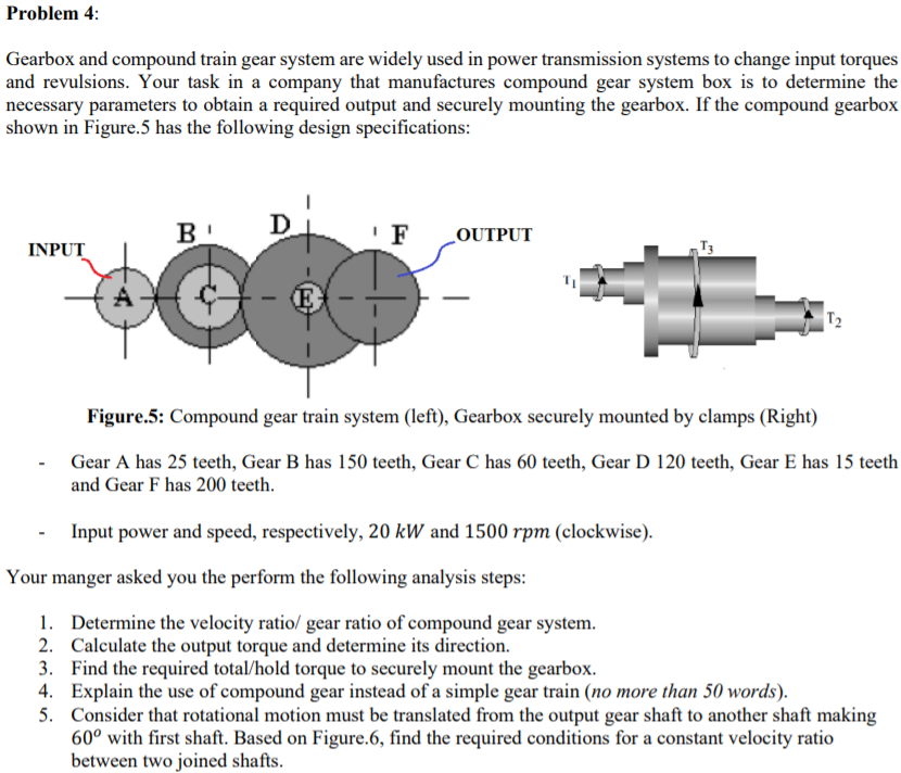
Transcribed Image Text:Problem 4:
Gearbox and compound train gear system are widely used in power transmission systems to change input torques
and revulsions. Your task in a company that manufactures compound gear system box is to determine the
necessary parameters to obtain a required output and securely mounting the gearbox. If the compound gearbox
shown in Figure.5 has the following design specifications:
B
D
' F
OUTPUT
INPUT
T3
A
T2
Figure.5: Compound gear train system (left), Gearbox securely mounted by clamps (Right)
Gear A has 25 teeth, Gear B has 150 teeth, Gear C has 60 teeth, Gear D 120 teeth, Gear E has 15 teeth
and Gear F has 200 teeth.
Input power and speed, respectively, 20 kW and 1500 rpm (clockwise).
Your manger asked you the perform the following analysis steps:
1. Determine the velocity ratio/ gear ratio of compound gear system.
2. Calculate the output torque and determine its direction.
3. Find the required total/hold torque to securely mount the gearbox.
4. Explain the use of compound gear instead of a simple gear train (no more than 50 words).
5. Consider that rotational motion must be translated from the output gear shaft to another shaft making
60° with first shaft. Based on Figure.6, find the required conditions for a constant velocity ratio
between two joined shafts.
Expert Solution
This question has been solved!
Explore an expertly crafted, step-by-step solution for a thorough understanding of key concepts.

Step by step
Solved in 6 steps with 5 images

Knowledge Booster


Learn more about
Need a deep-dive on the concept behind this application? Look no further. Learn more about this topic, mechanical-engineering and related others by exploring similar questions and additional content below.Recommended textbooks for you
Mechanics of Materials (MindTap Course List)
Mechanical Engineering
ISBN:
9781337093347
Author:
Barry J. Goodno, James M. Gere
Publisher:
Cengage Learning
Mechanics of Materials (MindTap Course List)
Mechanical Engineering
ISBN:
9781337093347
Author:
Barry J. Goodno, James M. Gere
Publisher:
Cengage Learning