P11_a, f= 5 kHz |VR| = P11_b, f= 70 kHz |VR| P11_c, f= 100 kHz |VR| = (mV) LVR= LVR= LVR= (deg.
P11_a, f= 5 kHz |VR| = P11_b, f= 70 kHz |VR| P11_c, f= 100 kHz |VR| = (mV) LVR= LVR= LVR= (deg.

Power System Analysis and Design (MindTap Course List)
6th Edition
ISBN:9781305632134
Author:J. Duncan Glover, Thomas Overbye, Mulukutla S. Sarma
Publisher:J. Duncan Glover, Thomas Overbye, Mulukutla S. Sarma
Chapter2: Fundamentals
Section: Chapter Questions
Problem 2.16P: A single-phase, 120V(rms),60Hz source supplies power to a series R-L circuit consisting of R=10 and...

Related questions
Question
Need Help with parts 11 and 12 please.
Thank you
Transcribed Image Text:P11 a, f= 5 kHz
|VR|
LVR=
LVR=.
LVR=
ZVR=
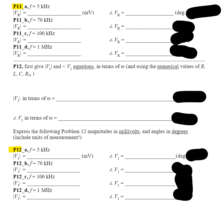
P12, first give |V₂| and < V₁ equations, in terms of @ (and using the numerical values of R,
L, C, Rin)
=
P11_b, f= 70 kHz
|VR|
P11_c, f= 100 kHz
|VR|
P11_d, f= 1 MHz
|VR|
=
=
=
V₁| in terms of co=
P12_a, f= 5 kHz
|V₂|
P12_b, f= 70 kHz
|V₂| =
P12_c, f= 100 kHz
|V₂|
P12_d, f= 1 MHz
|V₂|
V₁ in terms of =
Express the following Problem 12 magnitudes in millivolts, and angles in degrees
(include units of measurement!)
=
=
=
(mV)
=
(mV)
(deg.
LV₁ =
2 V₁ =
<V₂ = .
2 V₁ =
(deg
Transcribed Image Text:2. Recall the actual p-p voltage supplied by the signal generator is the open-circuit p-p voltage
as shown in Figure 1. (For the laboratory discovery, make sure the open-circuit p-p voltage is
2 volts before connecting the circuit elements (R, L, C) to build the circuit shown in Figure
1.) If we use an oscilloscope to measure the voltage across the generator, we are actually
measuring the voltage, V₁(t), across the terminals AB. If Vs (t) = cos(ot) volts (open-circuit
generator voltage), what is the phasor, V₁, of the measured voltage across the generator?
3. By inspection of the circuit, explain why the measured peak voltage across the generator
(peak of V₁(t)) is close to the peak voltage of Vs (t) (which is 1V) at low (DC) and high
frequencies.
4. Use the result in Q.1 to find the resonant frequency of the circuit when C= 4.7nF. L=1mH,
and R= 51 ohm.
5. For Vs (t) = cos(ot) volts, find |VR| and Z VR when f= 5 kHz, 70 kHz, 100 kHz and 1MHz
when C= 4.7nF. L=1mH, and R= 51 ohm.
6. Also find V, and ZV, when f= 5 kHz, 70 kHz, 100 kHz and 1MHz
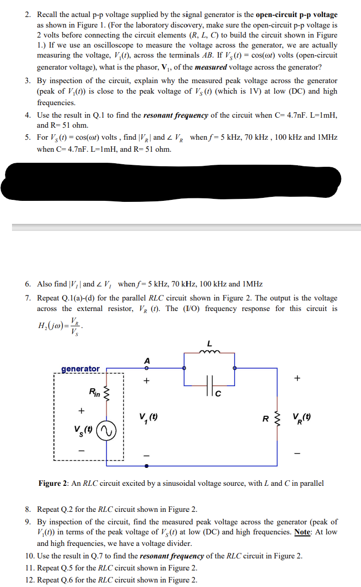
7. Repeat Q.1(a)-(d) for the parallel RLC circuit shown in Figure 2. The output is the voltage
across the external resistor, VR (t). The (I/O) frequency response for this circuit is
VR
H₂(jo)= V/
Vs
generator
+
Rin
A
+
V₁ (t)
L
R
+
Figure 2: An RLC circuit excited by a sinusoidal voltage source, with L and C in parallel
8. Repeat Q.2 for the RLC circuit shown in Figure 2.
9. By inspection of the circuit, find the measured peak voltage across the generator (peak of
V₁(t)) in terms of the peak voltage of Vs (t) at low (DC) and high frequencies. Note: At low
and high frequencies, we have a voltage divider.
10. Use the result in Q.7 to find the resonant frequency of the RLC circuit in Figure 2.
11. Repeat Q.5 for the RLC circuit shown in Figure 2.
12. Repeat Q.6 for the RLC circuit shown in Figure 2.
Expert Solution
This question has been solved!
Explore an expertly crafted, step-by-step solution for a thorough understanding of key concepts.

Step by step
Solved in 7 steps with 1 images

Knowledge Booster


Learn more about
Need a deep-dive on the concept behind this application? Look no further. Learn more about this topic, electrical-engineering and related others by exploring similar questions and additional content below.Recommended textbooks for you
Power System Analysis and Design (MindTap Course …
Electrical Engineering
ISBN:
9781305632134
Author:
J. Duncan Glover, Thomas Overbye, Mulukutla S. Sarma
Publisher:
Cengage Learning

Delmar's Standard Textbook Of Electricity
Electrical Engineering
ISBN:
9781337900348
Author:
Stephen L. Herman
Publisher:
Cengage Learning
Power System Analysis and Design (MindTap Course …
Electrical Engineering
ISBN:
9781305632134
Author:
J. Duncan Glover, Thomas Overbye, Mulukutla S. Sarma
Publisher:
Cengage Learning
Delmar's Standard Textbook Of Electricity
Electrical Engineering
ISBN:
9781337900348
Author:
Stephen L. Herman
Publisher:
Cengage Learning