P4. In the circuit of Figure 4, the independent source has voltage v, (1) = 200-/2 cos(10 t) V. (a) Using rms phasors, find the voltage vo(t) in the steady state as a sinusoidal function of time (Hint: apply nodal analysis). (b)Find the average and reactive powers supplied by the independent voltage source. 10 2 10 Q Figure 4 + v(1) + 2 mH v,(t) 10 µF 0.2V mell
P4. In the circuit of Figure 4, the independent source has voltage v, (1) = 200-/2 cos(10 t) V. (a) Using rms phasors, find the voltage vo(t) in the steady state as a sinusoidal function of time (Hint: apply nodal analysis). (b)Find the average and reactive powers supplied by the independent voltage source. 10 2 10 Q Figure 4 + v(1) + 2 mH v,(t) 10 µF 0.2V mell

Power System Analysis and Design (MindTap Course List)
6th Edition
ISBN:9781305632134
Author:J. Duncan Glover, Thomas Overbye, Mulukutla S. Sarma
Publisher:J. Duncan Glover, Thomas Overbye, Mulukutla S. Sarma
Chapter2: Fundamentals
Section: Chapter Questions
Problem 2.17MCQ: Consider the load convention that is used for the RLC elements shown in Figure 2.2 of the text. A....

Related questions

Question
i need help solving
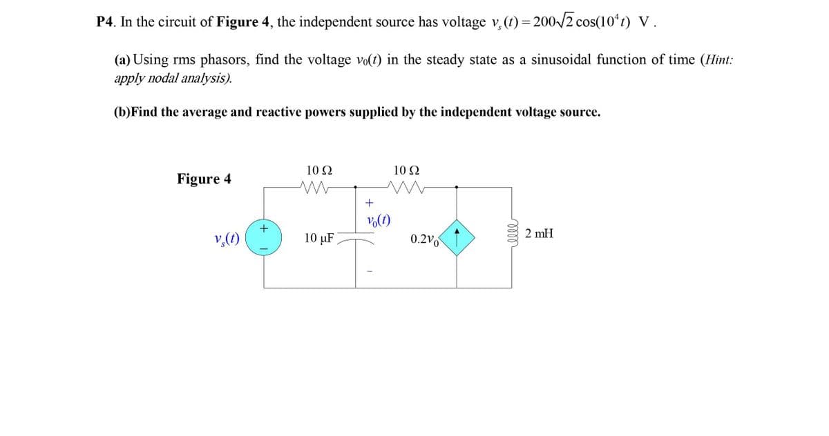
Transcribed Image Text:P4. In the circuit of Figure 4, the independent source has voltage v, (t) = 200/2 cos(10ʻt) V.
(a) Using rms phasors, find the voltage vo(t) in the steady state as a sinusoidal function of time (Hint:
apply nodal analysis).
(b)Find the average and reactive powers supplied by the independent voltage source.
10 2
10Ω
Figure 4
Vo(t)
+
2 mH
v,(1)
10 µF
0.2Vo
Expert Solution
This question has been solved!
Explore an expertly crafted, step-by-step solution for a thorough understanding of key concepts.

Step by step
Solved in 5 steps with 5 images

Knowledge Booster


Learn more about
Need a deep-dive on the concept behind this application? Look no further. Learn more about this topic, electrical-engineering and related others by exploring similar questions and additional content below.Recommended textbooks for you
Power System Analysis and Design (MindTap Course …
Electrical Engineering
ISBN:
9781305632134
Author:
J. Duncan Glover, Thomas Overbye, Mulukutla S. Sarma
Publisher:
Cengage Learning
Power System Analysis and Design (MindTap Course …
Electrical Engineering
ISBN:
9781305632134
Author:
J. Duncan Glover, Thomas Overbye, Mulukutla S. Sarma
Publisher:
Cengage Learning