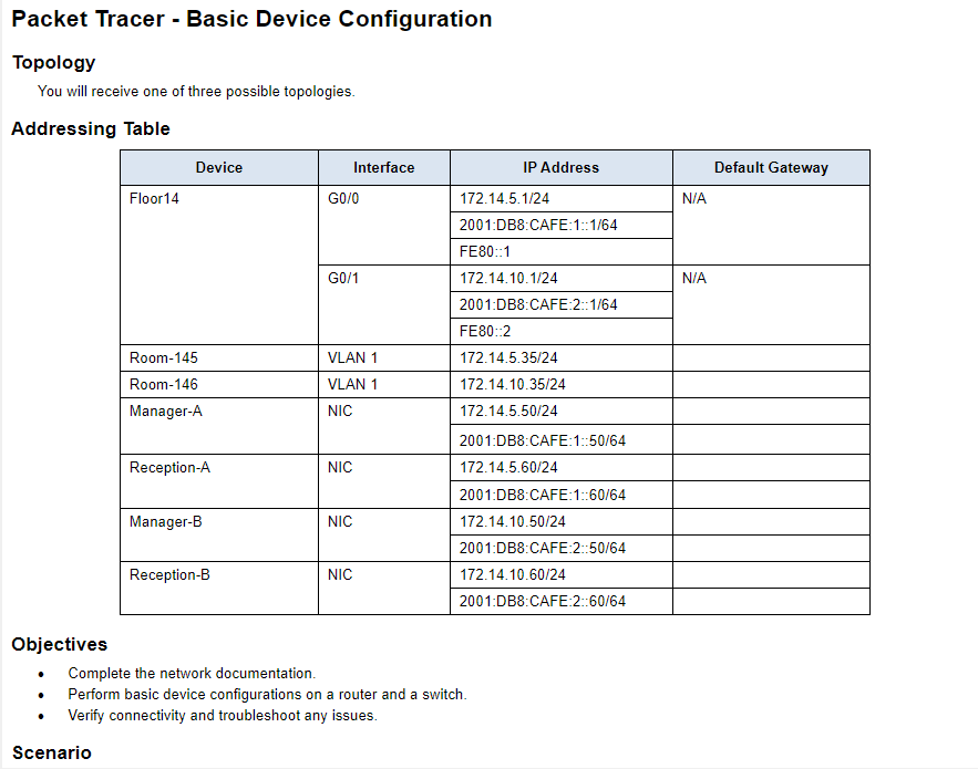
Packet Tracer - Basic Device Configuration Topology You will receive one of three possible topologies. Addressing Table Device Interface IP Address Default Gateway Floor14 G0/0 172.14.5.1/24 N/A 2001:DB8:CAFE:1::1/64 FE80::1 G0/1 172.14.10.1/24 2001:DB8:CAFE:2::1/64 FE80::2 Room-145 VLAN 1 172.14.5.35/24 Room-146 VLAN 1 172.14.10.35/24 Manager-A NIC 172.14.5.50/24 2001:DB8:CAFE:1::50/64 Reception-A NIC 172.14.5.60/24 2001:DB8:CAFE:1::60/64 Manager-B NIC 172.14.10.50/24 2001:DB8:CAFE:2::50/64 Reception-B NIC 172.14.10.60/24 2001:DB8:CAFE:2::60/64 Objectives Complete the network documentation. Perform basic device configurations on a router and a switch. Verify connectivity and troubleshoot any issues. Scenario N/A
Packet Tracer - Basic Device Configuration Topology You will receive one of three possible topologies. Addressing Table Device Interface IP Address Default Gateway Floor14 G0/0 172.14.5.1/24 N/A 2001:DB8:CAFE:1::1/64 FE80::1 G0/1 172.14.10.1/24 2001:DB8:CAFE:2::1/64 FE80::2 Room-145 VLAN 1 172.14.5.35/24 Room-146 VLAN 1 172.14.10.35/24 Manager-A NIC 172.14.5.50/24 2001:DB8:CAFE:1::50/64 Reception-A NIC 172.14.5.60/24 2001:DB8:CAFE:1::60/64 Manager-B NIC 172.14.10.50/24 2001:DB8:CAFE:2::50/64 Reception-B NIC 172.14.10.60/24 2001:DB8:CAFE:2::60/64 Objectives Complete the network documentation. Perform basic device configurations on a router and a switch. Verify connectivity and troubleshoot any issues. Scenario N/A

Chapter12: Network Configuration
Section: Chapter Questions
Problem 13RQ

Related questions
Question
Packet Tracer - Basic Device Configuration
10.4.3 Packet Tracer - Basic Device Configuration(1).pka
Topology
You will receive one of three possible topologies.
Addressing Table
Device
Interface
IP Address
Default Gateway
Floor14
G0/0
172.14.5.1/24
N/A
Floor14
G0/0
2001:DB8:CAFE:1::1/64
N/A
Floor14
G0/0
FE80::1
N/A
Floor14
G0/1
172.14.10.1/24
N/A
Floor14
G0/1
2001:DB8:CAFE:2::1/64
N/A
Floor14
G0/1
FE80::2
N/A
Room-145
VLAN 1
172.14.5.35/24
blank
Room-146
VLAN 1
172.14.10.35/24
blank
Manager-A
NIC
172.14.5.50/24
blank
Manager-A
NIC
2001:DB8:CAFE:1::50/64
blank
Reception-A
NIC
172.14.5.60/24
blank
Reception-A
NIC
2001:DB8:CAFE:1::60/64
blank
Manager-B
NIC
172.14.10.50/24
blank
Manager-B
NIC
2001:DB8:CAFE:2::50/64
blank
Reception-B
NIC
172.14.10.60/24
blank
Reception-B
NIC
2001:DB8:CAFE:2::60/64
blank
Objectives
· Complete the network documentation.
· Perform basic device configurations on a router and a switch.
· Verify connectivity and troubleshoot any issues.
Scenario
Your network manager is impressed with your performance in your job as a LAN technician. She would like you to demonstrate your ability to configure a router that connects two LANs. Your tasks include configuring basic settings on a router and a switch using the Cisco IOS. You will also configure IPv6 addresses on network devices and hosts. You will then verify the configurations by testing end-to-end connectivity. You goal is to establish connectivity between all devices.
Note: The VLAN1 interface on Room-145 will not be reachable over IPv6.
In this activity you will configure the Floor14 router, Room-146 switch, and the PC hosts.
Note: Packet Tracer will not score some configured values, however these values are required to accomplish full connectivity in the network.
Requirements
· Provide the missing information in the Addressing Table.
· Name the router Floor14 and the second switch Room-146. You will not be able to access the Room-145 switch.
· Use cisco as the user EXEC password for all lines.
· Use class as the encrypted privileged EXEC password.
· Encrypt all plaintext passwords.
· Configure an appropriate banner.
· Configure IPv4 and IPv6 addressing for the Floor14 switch according to the Addressing Table.
· Configure IPv4 and IPv6 addressing for the Room-146 switch according to the Addressing Table.
· The hosts are partially configured. Complete the IPv4 addressing, and fully configure the IPv6 addresses according to the Addressing Table.
· Document interfaces with descriptions, including the Room-146 VLAN 1 interface.
· Save your configurations.
· Verify connectivity between all devices. All devices should be able to ping all other devices with IPv4 and IPv6.
· Troubleshoot and document any issues.
· Implement the solutions necessary to enable and verify full end-to-end connectivity.
Note: Click Check Results button to see your progress. Click the Reset Activity button to generate a new set of requirements.
ID: 111
Transcribed Image Text:Packet Tracer - Basic Device Configuration
Topology
You will receive one of three possible topologies.
Addressing Table
Device
Interface
IP Address
Default Gateway
Floor14
G0/0
172.14.5.1/24
N/A
2001:DB8:CAFE:1::1/64
FE80::1
G0/1
172.14.10.1/24
2001:DB8:CAFE:2::1/64
FE80::2
Room-145
VLAN 1
172.14.5.35/24
Room-146
VLAN 1
172.14.10.35/24
Manager-A
NIC
172.14.5.50/24
2001:DB8:CAFE:1::50/64
Reception-A
NIC
172.14.5.60/24
2001:DB8:CAFE:1::60/64
Manager-B
NIC
172.14.10.50/24
2001:DB8:CAFE:2::50/64
Reception-B
NIC
172.14.10.60/24
2001:DB8:CAFE:2::60/64
Objectives
Complete the network documentation.
Perform basic device configurations on a router and a switch.
Verify connectivity and troubleshoot any issues.
Scenario
N/A
AI-Generated Solution

Unlock instant AI solutions
Tap the button
to generate a solution
Recommended textbooks for you
LINUX+ AND LPIC-1 GDE.TO LINUX CERTIF.
Computer Science
ISBN:
9781337569798
Author:
ECKERT
Publisher:
CENGAGE L
LINUX+ AND LPIC-1 GDE.TO LINUX CERTIF.
Computer Science
ISBN:
9781337569798
Author:
ECKERT
Publisher:
CENGAGE L