Parallel Circuit Determine the total current in this circuit Enter Your Answers Below Don't Enter Units Current (A): Rw R2 R1 56 Ω 94 Ω www 26 Ω 24 V Submit
Parallel Circuit Determine the total current in this circuit Enter Your Answers Below Don't Enter Units Current (A): Rw R2 R1 56 Ω 94 Ω www 26 Ω 24 V Submit

Delmar's Standard Textbook Of Electricity
7th Edition
ISBN:9781337900348
Author:Stephen L. Herman
Publisher:Stephen L. Herman
Chapter18: Resistive-inductive Parallel Circuits
Section: Chapter Questions
Problem 16PP: An R-L parallel circuit has an applied voltage of 208 volts and a total current of 2 amperes. The...

Related questions
Question
Asap plzz
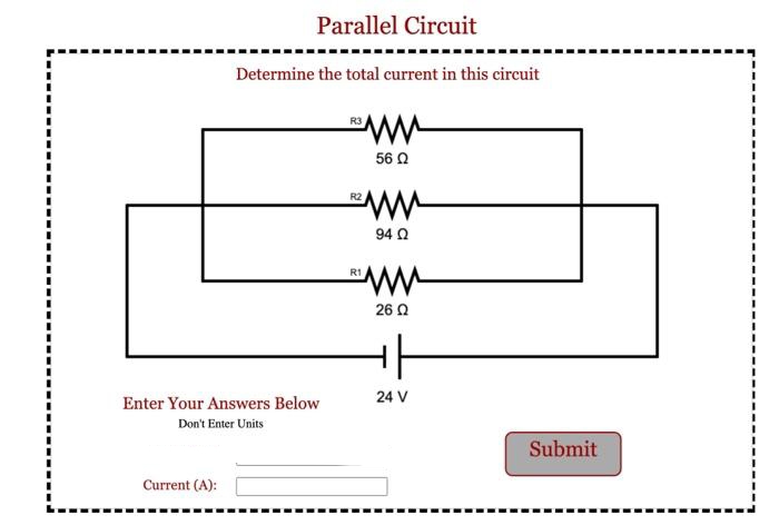
Transcribed Image Text:Parallel Circuit
Determine the total current in this circuit
Enter Your Answers Below
Don't Enter Units
Current (A):
ww
56 Ω
R2
www
94 Ω
R1
ww
26 Ω
24 V
Submit
Expert Solution
This question has been solved!
Explore an expertly crafted, step-by-step solution for a thorough understanding of key concepts.

Step by step
Solved in 2 steps with 2 images

Knowledge Booster


Learn more about
Need a deep-dive on the concept behind this application? Look no further. Learn more about this topic, electrical-engineering and related others by exploring similar questions and additional content below.Recommended textbooks for you
Delmar's Standard Textbook Of Electricity
Electrical Engineering
ISBN:
9781337900348
Author:
Stephen L. Herman
Publisher:
Cengage Learning
Delmar's Standard Textbook Of Electricity
Electrical Engineering
ISBN:
9781337900348
Author:
Stephen L. Herman
Publisher:
Cengage Learning