Part 1: Design a 4-bit synchronous counter that counts in 2,4,2,1 code. The counter shall count all BCD Even numbers in the 2,4,2,1 code. Use the minimum number of clocked JK flip flops and any necessary logic gates to build this counter. Note: treating the unused state don't care conditions.
Part 1: Design a 4-bit synchronous counter that counts in 2,4,2,1 code. The counter shall count all BCD Even numbers in the 2,4,2,1 code. Use the minimum number of clocked JK flip flops and any necessary logic gates to build this counter. Note: treating the unused state don't care conditions.

Chapter22: Sequence Control
Section: Chapter Questions
Problem 6SQ: Draw a symbol for a solid-state logic element AND.

Related questions
Question
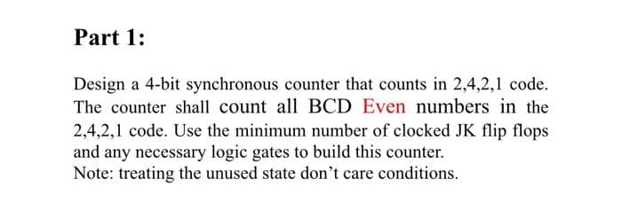
Transcribed Image Text:Part 1:
Design a 4-bit synchronous counter that counts in 2,4,2,1 code.
The counter shall count all BCD Even numbers in the
2,4,2,1 code. Use the minimum number of clocked JK flip flops
and any necessary logic gates to build this counter.
Note: treating the unused state don't care conditions.

Transcribed Image Text:6. Plot the logic circuit of your counter.
Expert Solution
This question has been solved!
Explore an expertly crafted, step-by-step solution for a thorough understanding of key concepts.

This is a popular solution!

Trending now
This is a popular solution!

Step by step
Solved in 2 steps with 2 images

Knowledge Booster


Learn more about
Need a deep-dive on the concept behind this application? Look no further. Learn more about this topic, electrical-engineering and related others by exploring similar questions and additional content below.Recommended textbooks for you