Part 1 Rigid bar ABC is supported by bronze rod (1) and aluminum rod (2), as shown. A concentrated load P is applied to the free end of aluminum rod (3). Bronze rod (1) has an elastic modulus of E₁ = 15,000 ksi and a diameter of d₁ = 0.40 in. Aluminum rod (2) has an elastic modulus of E₂ = 10,000 ksi and a diameter of d₂ = 0.70in. Aluminum rod (3) has a diameter of d3 = 1.00in. The yield strength of the bronze is 48 ksi and the yield strength of the aluminum is 40 ksi. Assume a = 2.5 ft, b = 1.5 ft, L₁= 6 ft, L₂= 8 ft, and L3 = 3 ft. (a) Determine the magnitude of load P that can safely be applied to the structure if a minimum factor of safety of 1.8 is required. (b) Determine the deflection of point D for the load determined in part (a). (c) The pin used at B has an ultimate shear strength of 57 ksi. If a factor of safety of 2.7 is required for this double shear pin connection, determine the minimum pin diameter that can be used at B. LI T A Bronze (1) B Aluminum (3) D Aluminum (2) P b L3 C L2
Part 1 Rigid bar ABC is supported by bronze rod (1) and aluminum rod (2), as shown. A concentrated load P is applied to the free end of aluminum rod (3). Bronze rod (1) has an elastic modulus of E₁ = 15,000 ksi and a diameter of d₁ = 0.40 in. Aluminum rod (2) has an elastic modulus of E₂ = 10,000 ksi and a diameter of d₂ = 0.70in. Aluminum rod (3) has a diameter of d3 = 1.00in. The yield strength of the bronze is 48 ksi and the yield strength of the aluminum is 40 ksi. Assume a = 2.5 ft, b = 1.5 ft, L₁= 6 ft, L₂= 8 ft, and L3 = 3 ft. (a) Determine the magnitude of load P that can safely be applied to the structure if a minimum factor of safety of 1.8 is required. (b) Determine the deflection of point D for the load determined in part (a). (c) The pin used at B has an ultimate shear strength of 57 ksi. If a factor of safety of 2.7 is required for this double shear pin connection, determine the minimum pin diameter that can be used at B. LI T A Bronze (1) B Aluminum (3) D Aluminum (2) P b L3 C L2

Chapter2: Loads On Structures
Section: Chapter Questions
Problem 1P

Related questions

Question
Transcribed Image Text:Part 1
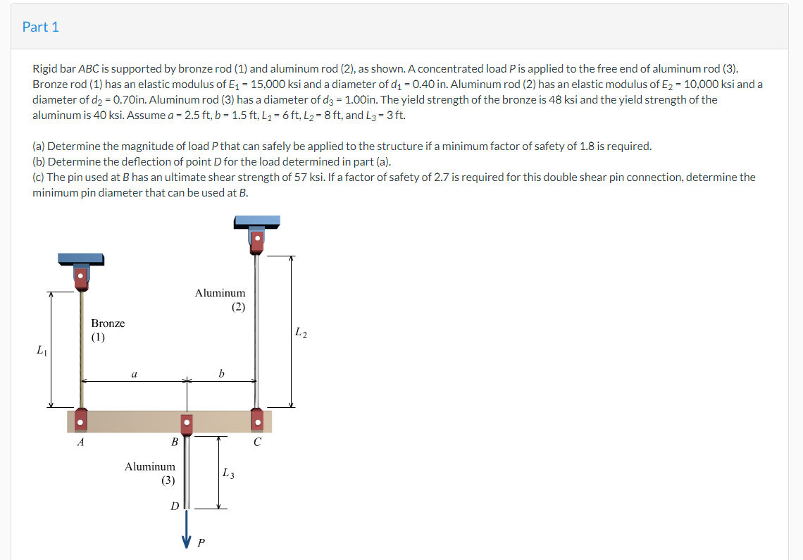
Rigid bar ABC is supported by bronze rod (1) and aluminum rod (2), as shown. A concentrated load P is applied to the free end of aluminum rod (3).
Bronze rod (1) has an elastic modulus of E₁ = 15,000 ksi and a diameter of d₁ = 0.40 in. Aluminum rod (2) has an elastic modulus of E₂ = 10,000 ksi and a
diameter of d₂ = 0.70in. Aluminum rod (3) has a diameter of d3 = 1.00in. The yield strength of the bronze is 48 ksi and the yield strength of the
aluminum is 40 ksi. Assume a = 2.5 ft, b = 1.5 ft, L₁= 6 ft, L₂= 8 ft, and L3 = 3 ft.
(a) Determine the magnitude of load P that can safely be applied to the structure if a minimum factor of safety of 1.8 is required.
(b) Determine the deflection of point D for the load determined in part (a).
(c) The pin used at B has an ultimate shear strength of 57 ksi. If a factor of safety of 2.7 is required for this double shear pin connection, determine the
minimum pin diameter that can be used at B.
LI
T
A
Bronze
(1)
B
Aluminum
(3)
D
Aluminum
(2)
P
b
L3
C
L2

Transcribed Image Text:Calculate the cross-sectional areas of the three rods.
Answers:
A₁ =
A₂ =
A3 =
Part 2
Answers:
allow,Br=
For a factor of safety of 1.8, calculate the allowable stresses in the bronze and the aluminum rods.
Gallow,Al =
Part 3
Answers:
P/F₁ =
in.²
P/F₂ =
in.2
P/F3 =
in.²
On a piece of paper, sketch a free body diagram (FBD) cut through rod (3) and also a FBD of the rigid bar. Using these, find a relationship between the force in rod 1 (F₁) and the applied load, P, a relationship between the force in rod 2 (F₂) and the applied load, P, and also a relationship between the force in
rod 3 (F3) and the applied load, P.
ksi
ksi
Expert Solution
This question has been solved!
Explore an expertly crafted, step-by-step solution for a thorough understanding of key concepts.

This is a popular solution!

Trending now
This is a popular solution!

Step by step
Solved in 2 steps with 2 images

Knowledge Booster


Learn more about
Need a deep-dive on the concept behind this application? Look no further. Learn more about this topic, civil-engineering and related others by exploring similar questions and additional content below.Recommended textbooks for you

Structural Analysis (10th Edition)
Civil Engineering
ISBN:
9780134610672
Author:
Russell C. Hibbeler
Publisher:
PEARSON

Principles of Foundation Engineering (MindTap Cou…
Civil Engineering
ISBN:
9781337705028
Author:
Braja M. Das, Nagaratnam Sivakugan
Publisher:
Cengage Learning
Structural Analysis (10th Edition)
Civil Engineering
ISBN:
9780134610672
Author:
Russell C. Hibbeler
Publisher:
PEARSON
Principles of Foundation Engineering (MindTap Cou…
Civil Engineering
ISBN:
9781337705028
Author:
Braja M. Das, Nagaratnam Sivakugan
Publisher:
Cengage Learning

Fundamentals of Structural Analysis
Civil Engineering
ISBN:
9780073398006
Author:
Kenneth M. Leet Emeritus, Chia-Ming Uang, Joel Lanning
Publisher:
McGraw-Hill Education


Traffic and Highway Engineering
Civil Engineering
ISBN:
9781305156241
Author:
Garber, Nicholas J.
Publisher:
Cengage Learning