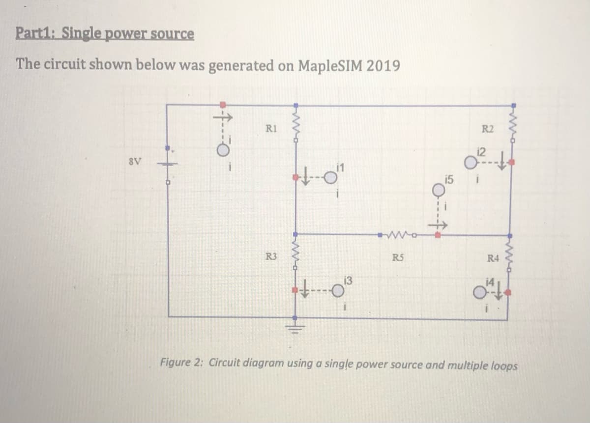
Part1: Single power source The circuit shown below was generated on MapleSIM 2019 R1 R2 i2 SV i5 R3 R5 R4 Figure 2: Circuit diagram using a single power source and multiple loops

Introductory Circuit Analysis (13th Edition)
13th Edition
ISBN:9780133923605
Author:Robert L. Boylestad
Publisher:Robert L. Boylestad
Chapter1: Introduction
Section: Chapter Questions
Problem 1P: Visit your local library (at school or home) and describe the extent to which it provides literature...
icon
Related questions
icon
Concept explainers
Question
100%
Pls show calculations
Part1: Single power source
The circuit shown below was generated on MapleSIM 2019
R1
R2
8V
i5
R3
R5
R4
Figure 2: Circuit diagram using a single power source and multiple loops
Transcribed Image Text:Part1: Single power source The circuit shown below was generated on MapleSIM 2019 R1 R2 8V i5 R3 R5 R4 Figure 2: Circuit diagram using a single power source and multiple loops
In the above circuit, R1=202, R2=502, R3=1002, R4=25, and Rs=750. The response of this
circuit (Fig 2.), i.e., the values of the probes measuring currents was simulated for a total time of
10s. The simulated data is shown below
Analysis Window: Simulation Results
Simulation Results
Probe Plots
Iv Stored Results
RRE
ii
ili
12i
la "One power supply multiple lo
VLatest Resuts
0.105
0.205
0.110
0.200-
0.100
0.105
0.195
0.100
07
V Variables: One power supply mul.
g0.095
0.190
0.095-
Find:
0.185
0.090
0.090
Main
0.180
0.085
0.085
0.175
12
13
4.2 4.6 5.0 54 5.8
3.5 4 4.5 5 5.56 6.5
4
4.5
5.5
6
15
13.i
14i
15 i
0.075
0.0501
0.145
V Plot Windows: One power supply..
0.070
0.045
0.140
0.065
0.135
0.040
E v 11.1
v 12.1
v 13.
v 14.1
m0.060
0.1304
0.035
0.055
0.125
0.030
0.050
0.120
0.115
0.025
4.
7.
4 4.5 5 5.5
6.
23
45
6 7 8
Figure 3: Simulated current response for circuit shown in Fig 2.
In the simulation data presented above, the currents on the axes are in amperes (A). Usually the
least count of most ammeters is 1mA, hence the significant figures on the current measurements
were set to 0.001A (please follow the rules of significant figures).
1. From the data above, report the experimentally simulated values for
a. Current through resistor R1:
b. Current through resistor R2:
c. Current through resistor R3:
d. Current through resistor R4:
Transcribed Image Text:In the above circuit, R1=202, R2=502, R3=1002, R4=25, and Rs=750. The response of this circuit (Fig 2.), i.e., the values of the probes measuring currents was simulated for a total time of 10s. The simulated data is shown below Analysis Window: Simulation Results Simulation Results Probe Plots Iv Stored Results RRE ii ili 12i la "One power supply multiple lo VLatest Resuts 0.105 0.205 0.110 0.200- 0.100 0.105 0.195 0.100 07 V Variables: One power supply mul. g0.095 0.190 0.095- Find: 0.185 0.090 0.090 Main 0.180 0.085 0.085 0.175 12 13 4.2 4.6 5.0 54 5.8 3.5 4 4.5 5 5.56 6.5 4 4.5 5.5 6 15 13.i 14i 15 i 0.075 0.0501 0.145 V Plot Windows: One power supply.. 0.070 0.045 0.140 0.065 0.135 0.040 E v 11.1 v 12.1 v 13. v 14.1 m0.060 0.1304 0.035 0.055 0.125 0.030 0.050 0.120 0.115 0.025 4. 7. 4 4.5 5 5.5 6. 23 45 6 7 8 Figure 3: Simulated current response for circuit shown in Fig 2. In the simulation data presented above, the currents on the axes are in amperes (A). Usually the least count of most ammeters is 1mA, hence the significant figures on the current measurements were set to 0.001A (please follow the rules of significant figures). 1. From the data above, report the experimentally simulated values for a. Current through resistor R1: b. Current through resistor R2: c. Current through resistor R3: d. Current through resistor R4:
Expert Solution
trending now

Trending now

This is a popular solution!

steps

Step by step

Solved in 3 steps with 3 images

Blurred answer
Knowledge Booster
8085 Microprocessor
Learn more about
Need a deep-dive on the concept behind this application? Look no further. Learn more about this topic, electrical-engineering and related others by exploring similar questions and additional content below.
Similar questions
  • SEE MORE QUESTIONS
Recommended textbooks for you
Introductory Circuit Analysis (13th Edition)
Electrical Engineering
ISBN:
9780133923605
Author:
Robert L. Boylestad
Publisher:
PEARSON
Delmar's Standard Textbook Of Electricity
Electrical Engineering
ISBN:
9781337900348
Author:
Stephen L. Herman
Publisher:
Cengage Learning
Programmable Logic Controllers
Electrical Engineering
ISBN:
9780073373843
Author:
Frank D. Petruzella
Publisher:
McGraw-Hill Education
Fundamentals of Electric Circuits
Electrical Engineering
ISBN:
9780078028229
Author:
Charles K Alexander, Matthew Sadiku
Publisher:
McGraw-Hill Education
Electric Circuits. (11th Edition)
Electrical Engineering
ISBN:
9780134746968
Author:
James W. Nilsson, Susan Riedel
Publisher:
PEARSON
Engineering Electromagnetics
Electrical Engineering
ISBN:
9780078028151
Author:
Hayt, William H. (william Hart), Jr, BUCK, John A.
Publisher:
Mcgraw-hill Education,