Please enter your answer in the blank's: Voltage at load bus, VLoad = ° p.u. Motor apparent power, SM= * p.u. Current drawn by the motor, Im= p.u. Current drawn by the load, ILoad= p.u. Total current drawn by load bus, I7= 'p. Equivalent series impedance, Z7 = * p.u. Voltage at generator busbar V, = p.u. Voltage at generator busbar V, = • kV

Power System Analysis and Design (MindTap Course List)
6th Edition
ISBN:9781305632134
Author:J. Duncan Glover, Thomas Overbye, Mulukutla S. Sarma
Publisher:J. Duncan Glover, Thomas Overbye, Mulukutla S. Sarma
Chapter3: Power Transformers
Section: Chapter Questions
Problem 3.23P: Figure 3.32 shows the oneline diagram of a three-phase power system. By selecting a common base of...
icon
Related questions
icon
Concept explainers
Question
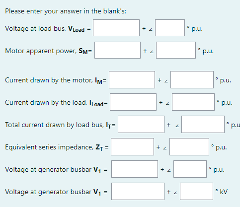
Please enter your answer in the blank's:
° p.u.
Voltage at load bus, VLoad =
• p.u.
Motor apparent power, SM=
° p.u.
Current drawn by the motor, Im=
p.u.
Current drawn by the load, ILoad=
p.u
Total current drawn by load bus, I7=
p.u.
Equivalent series impedance, ZT =
° p.u.
Voltage at generator busbar V, =
• kV
Voltage at generator busbar V1 =
Transcribed Image Text:Please enter your answer in the blank's: ° p.u. Voltage at load bus, VLoad = • p.u. Motor apparent power, SM= ° p.u. Current drawn by the motor, Im= p.u. Current drawn by the load, ILoad= p.u Total current drawn by load bus, I7= p.u. Equivalent series impedance, ZT = ° p.u. Voltage at generator busbar V, = • kV Voltage at generator busbar V1 =
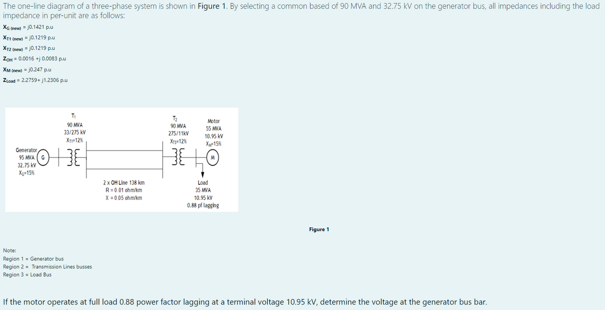
The one-line diagram of a three-phase system is shown in Figure 1. By selecting a common based of 90 MVA and 32.75 kV on the generator bus, all impedances including the load
impedance in per-unit are as follows:
XG (new) = j0.1421 p.u
XT1 (new) = j0.1219 p.u
XT2 (new) = j0.1219 p.u
ZOH = 0.0016 +j 0.0083 p.u
Хм пеw) 3D j0.247 р.u
ZLoad = 2.2759+ j1.2306 p.u
T1
T2
90 MVA
Motor
90 MVA
55 MVA
33/275 kV
275/11kV
10.95 kV
XT=12%
Xr3=12%
Xx=15%
Generator
95 MVA
M
32.75 kV
Xg=15%
2 x OH Line 138 km
R = 0.01 ohm/km
X = 0.05 ohm/km
Load
35 MVA
10.95 kV
0.88 pf lagging
Figure 1
Note:
Region 1 = Generator bus
Region 2 = Transmission Lines busses
Region 3 = Load Bus
If the motor operates at full load 0.88 power factor lagging at a terminal voltage 10.95 kV, determine the voltage at the generator bus bar.
Transcribed Image Text:The one-line diagram of a three-phase system is shown in Figure 1. By selecting a common based of 90 MVA and 32.75 kV on the generator bus, all impedances including the load impedance in per-unit are as follows: XG (new) = j0.1421 p.u XT1 (new) = j0.1219 p.u XT2 (new) = j0.1219 p.u ZOH = 0.0016 +j 0.0083 p.u Хм пеw) 3D j0.247 р.u ZLoad = 2.2759+ j1.2306 p.u T1 T2 90 MVA Motor 90 MVA 55 MVA 33/275 kV 275/11kV 10.95 kV XT=12% Xr3=12% Xx=15% Generator 95 MVA M 32.75 kV Xg=15% 2 x OH Line 138 km R = 0.01 ohm/km X = 0.05 ohm/km Load 35 MVA 10.95 kV 0.88 pf lagging Figure 1 Note: Region 1 = Generator bus Region 2 = Transmission Lines busses Region 3 = Load Bus If the motor operates at full load 0.88 power factor lagging at a terminal voltage 10.95 kV, determine the voltage at the generator bus bar.
Expert Solution
steps

Step by step

Solved in 3 steps with 5 images

Blurred answer
Knowledge Booster
Load flow analysis
Learn more about
Need a deep-dive on the concept behind this application? Look no further. Learn more about this topic, electrical-engineering and related others by exploring similar questions and additional content below.
Similar questions
  • SEE MORE QUESTIONS
Recommended textbooks for you
Power System Analysis and Design (MindTap Course …
Electrical Engineering
ISBN:
9781305632134
Author:
J. Duncan Glover, Thomas Overbye, Mulukutla S. Sarma
Publisher:
Cengage Learning