Plot a graph of voltage (ordinate or vertical axis) and current (abscissa or horizontal axis), and determine the resistance constant value by computing the slope of the best straight line through the points.
Plot a graph of voltage (ordinate or vertical axis) and current (abscissa or horizontal axis), and determine the resistance constant value by computing the slope of the best straight line through the points.

Chapter7: Electricity
Section: Chapter Questions
Problem 35Q: (Indicates a review question, which means it requires only a basic understanding of the material to...

Related questions
Question
I want to solve a graph and discuss Ohm's law
Transcribed Image Text:Experiment number (1)
Ohm's Law
Objective:
Verifying Ohm's Law and determine the resistance constant value.
Apparatus:
Power supply, ammeter, voltmeter, resistance, conducting wires.
Theory:
Georg Simon Ohm (1787-1854), a German physicist, discovered Ohm's law in
1826. This is an experimental law, valid for both alternating current (ac) and
direct current (de) circuits.
When you pass an electric current (I) through a resistance (R) there will be an
electric potential difference (V) created across the resistance as shown below.
Ohm's law gives a relationship between V, I aud R as follows.
V=IR
Units: V- volt (V), I- ampere (A), Rohm (N).
So Ohm's law states that the current through a conductor between two points is
directly proportional to the potential difference or voltage across the two points,
and inversely proportional to the resistance between them.
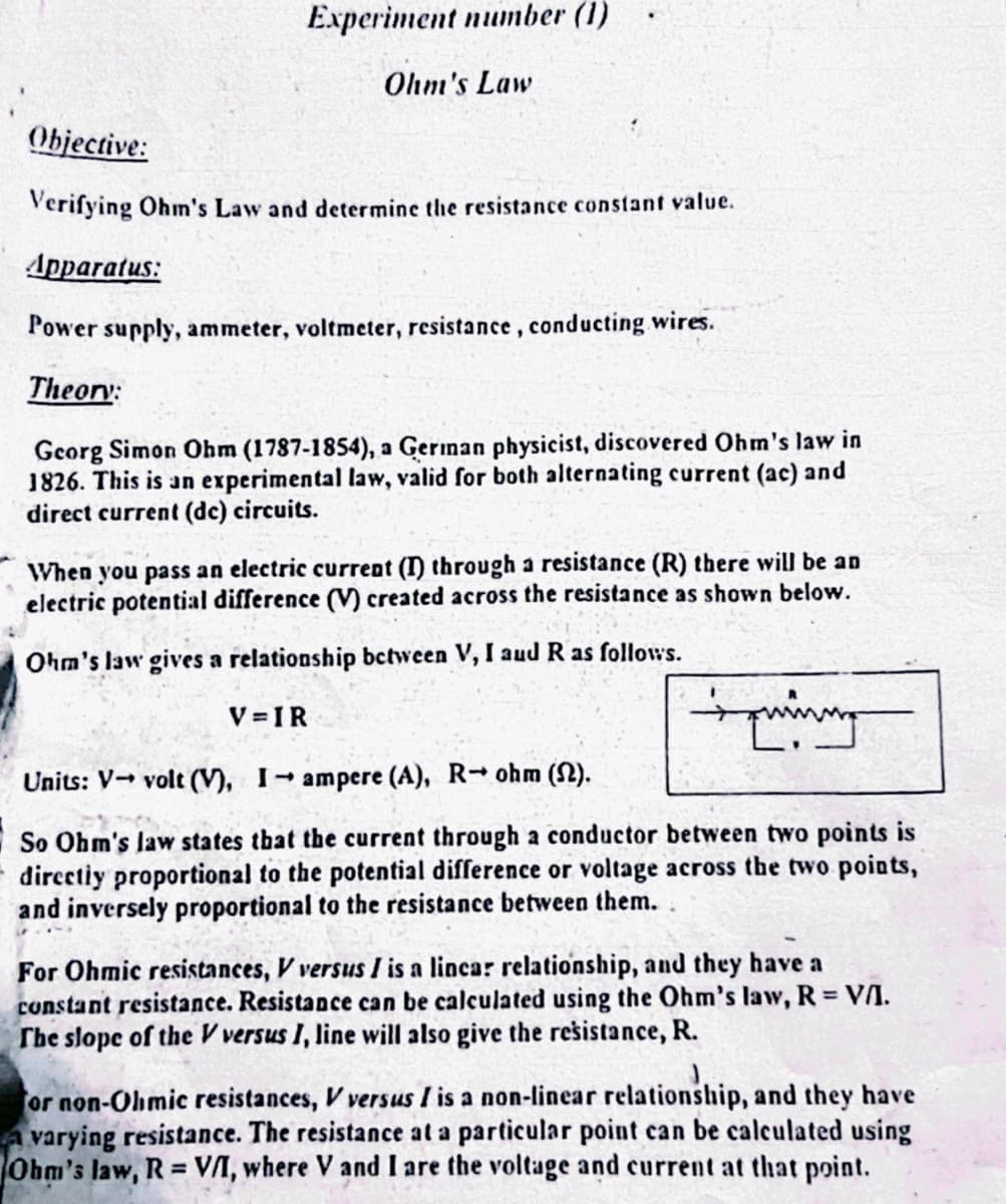
For Ohmic resistances, Vversus I is a lincar relationship, and they have a
constant resistance. Resistance can be calculated using the Ohm's law, R = VII.
The slope of the V versus I, line will also give the resistance, R.
or non-Ohmic resistances, V versus I is a non-linear relationship, and they have
A varying resistance. The resistance at a particular point can be calculated using
Ohm's law, R = V/I, where V and I are the voltage and current at that point.
Transcribed Image Text:Stop - R
V
Hon-chumic
A
2
6
ہم
8
+100
12
Fig (1): the relation between the Ohmic & non - Ohmic resistance.
The electrical resistance (R) of a device is defined to be the ratio of the voltage
(V) across the device to the current (i) through the device R = V/I. The unit of
resistance, ohm (2, the Greek letter capital omega), is then defined to be the
resistance when one volt exists across and one amp flows through the device, 2 =
YIA.
V
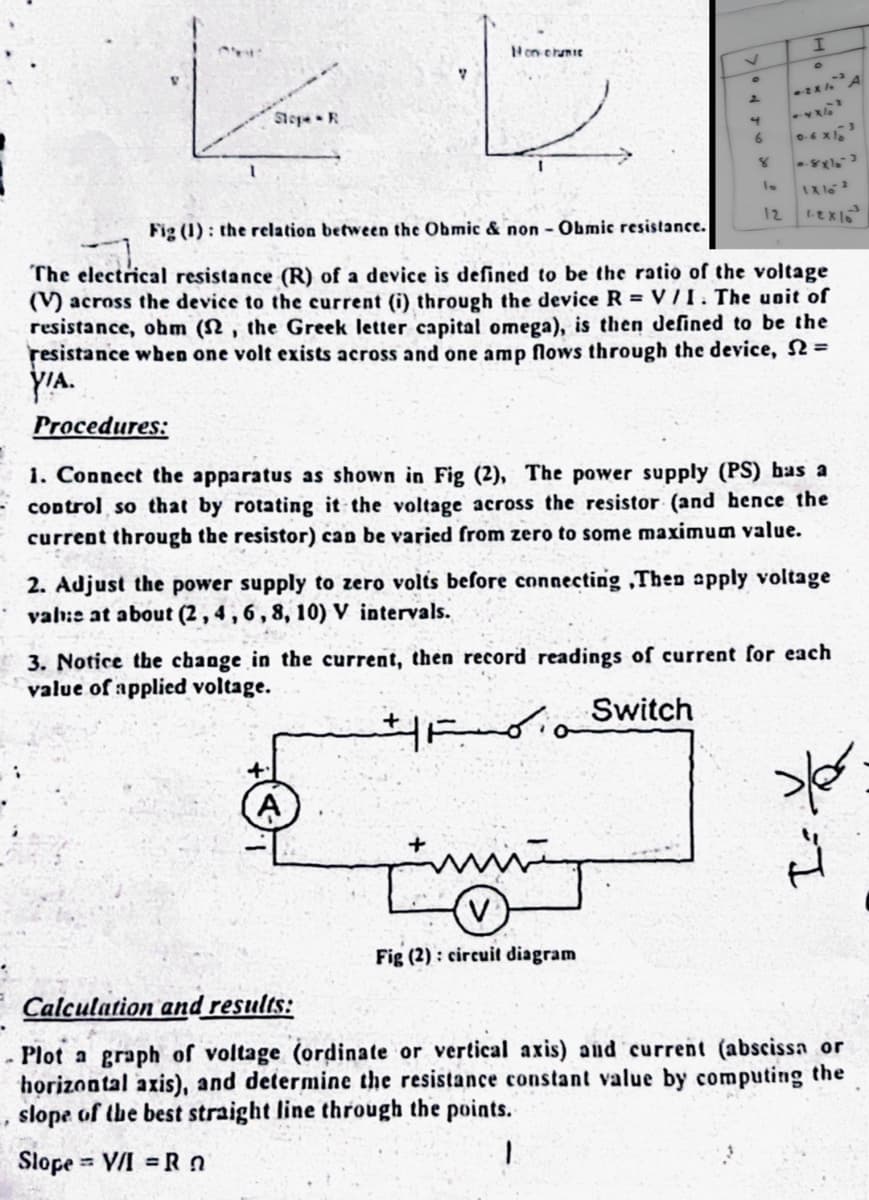
Fig (2): circuit diagram
I
Procedures:
i. Connect the apparatus as shown in Fig (2), The power supply (PS) has a
control so that by rotating it the voltage across the resistor (and hence the
current through the resistor) can be varied from zero to some maximum value.
2x A
2. Adjust the power supply to zero volts before connecting ,Then apply voltage
vab:e at about (2, 4, 6, 8, 10) V intervals.
8x1₂-3
1X10²
1.Exlo
3. Notice the change in the current, then record readings of current for each
value of applied voltage.
Switch
pler
Calculation and results:
Plot a graph of voltage (ordinate or vertical axis) and current (abscissa or
horizontal axis), and determine the resistance constant value by computing the
slope of the best straight line through the points.
Slope V/I=Rn
Expert Solution
This question has been solved!
Explore an expertly crafted, step-by-step solution for a thorough understanding of key concepts.

Step by step
Solved in 3 steps with 3 images

Knowledge Booster


Learn more about
Need a deep-dive on the concept behind this application? Look no further. Learn more about this topic, physics and related others by exploring similar questions and additional content below.Recommended textbooks for you

College Physics
Physics
ISBN:
9781938168000
Author:
Paul Peter Urone, Roger Hinrichs
Publisher:
OpenStax College

Physics for Scientists and Engineers, Technology …
Physics
ISBN:
9781305116399
Author:
Raymond A. Serway, John W. Jewett
Publisher:
Cengage Learning
College Physics
Physics
ISBN:
9781938168000
Author:
Paul Peter Urone, Roger Hinrichs
Publisher:
OpenStax College
Physics for Scientists and Engineers, Technology …
Physics
ISBN:
9781305116399
Author:
Raymond A. Serway, John W. Jewett
Publisher:
Cengage Learning


Glencoe Physics: Principles and Problems, Student…
Physics
ISBN:
9780078807213
Author:
Paul W. Zitzewitz
Publisher:
Glencoe/McGraw-Hill