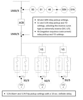
Problem 1 – The 4.16kV distribution station capacitor bank below consists of 3 ungrounded double-wye (UGDY) stages with a main breaker connecting Stage 1 capacitors directly and with Stages 2 and 3 through vacuum switches. Capacitor Unit Ratings: 2.400kV, 200kVAR CT Data: Main Breaker: 1500/5, Neutral CT: 50/5 Schweitzer SEL-351 Relay Data: Inst. Overcurrent Pickup Range: 0.25–100.00 A, 0.01 A steps Time Overcurrent Pickup Range: 0.25–16.00 A, 0.01 A steps Time-Dial Range: 0.50–15.00, 0.01 steps (US Curves) Inverse Delay Curve: US-U4 (Extremely Inverse) selected. a) Specify an appropriate K-Link expulsion fuse for individual capacitor units based on IEEE Std 18 overload requirements. HINT: The MMT curve fine print indicates that while the fuse melting curve starts well above the fuse’s nominal current rating, the fuse should not be overload on a normal basis without also derating it. b) For the main breaker relays, specify settings for each of the relay functions indicated above. Clearly state your basis for each setting. HINT: Recall that a relay must do two things – see faults AND carry the load. Check to see if your 51 function can detect a rack fault (i.e. shorted series group). With the 51 relay you may observe a peculiar difficulty with choosing a pickup setting which the 46 relay resolves. c) The 51N-1, -2, -3 relays have dual pickup settings so specify settings for each of the relay functions indicated above. Clearly state your basis for each. Note that all three relays will have identical settings.


Problem 1 – The 4.16kV distribution station capacitor bank below consists of 3 ungrounded double-wye (UGDY) stages with a main breaker connecting Stage 1 capacitors directly and with Stages 2 and 3 through vacuum switches.
Capacitor Unit Ratings: 2.400kV, 200kVAR
CT Data: Main Breaker: 1500/5, Neutral CT: 50/5
Schweitzer SEL-351 Relay Data: Inst. Overcurrent Pickup Range: 0.25–100.00 A, 0.01 A steps
Time Overcurrent Pickup Range: 0.25–16.00 A, 0.01 A steps
Time-Dial Range: 0.50–15.00, 0.01 steps (US Curves)
Inverse Delay Curve: US-U4 (Extremely Inverse) selected.
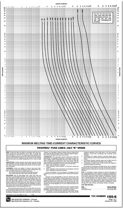
a) Specify an appropriate K-Link expulsion fuse for individual capacitor units based on IEEE Std 18 overload requirements.
HINT: The MMT curve fine print indicates that while the fuse melting curve starts well above the fuse’s nominal current rating, the fuse should not be overload on a normal basis without also derating it.
b) For the main breaker relays, specify settings for each of the relay functions indicated above. Clearly state your basis for each setting.
HINT: Recall that a relay must do two things – see faults AND carry the load. Check to see if your 51 function can detect a rack fault (i.e. shorted series group). With the 51 relay you may observe a peculiar difficulty with choosing a pickup setting which the 46 relay resolves.
c) The 51N-1, -2, -3 relays have dual pickup settings so specify settings for each of the relay functions indicated above. Clearly state your basis for each. Note that all three relays will have identical settings.


Trending now
This is a popular solution!

Step by step
Solved in 3 steps


