Problem 2 Cascaded Op Amp System Assume ideal operational amplifiers therefore you can use summing point constraints. Write time-domain equations for v3(t), v4(t), and v5(t) in terms of the circuit elements. Observe, no calculations are required. R3 v1(t) = C1 v3(t) v1(t) v2(t) = R1 R4 v4(t) v2(t) v3(t) = R2 v4(t) = v5(t) v5(t) =
Problem 2 Cascaded Op Amp System Assume ideal operational amplifiers therefore you can use summing point constraints. Write time-domain equations for v3(t), v4(t), and v5(t) in terms of the circuit elements. Observe, no calculations are required. R3 v1(t) = C1 v3(t) v1(t) v2(t) = R1 R4 v4(t) v2(t) v3(t) = R2 v4(t) = v5(t) v5(t) =

Delmar's Standard Textbook Of Electricity
7th Edition
ISBN:9781337900348
Author:Stephen L. Herman
Publisher:Stephen L. Herman
Chapter18: Resistive-inductive Parallel Circuits
Section: Chapter Questions
Problem 13PP: In an R-L parallel circuit, IT=1.25 amps, R=1.2k, and XL=1k. Find IR

Related questions
Question
2
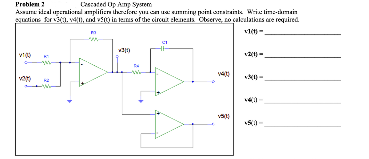
Transcribed Image Text:Problem 2
Cascaded Op Amp System
Assume ideal operational amplifiers therefore you can use summing point constraints. Write time-domain
equations for v3(t), v4(t), and v5(t) in terms of the circuit elements. Observe, no calculations are required.
R3
v1(t) =
C1
v3(t)
v1(t)
v2(t) =
R1
R4
v4(t)
v2(t)
v3(t) =
R2
v4(t) =
v5(t)
v5(t) =
Expert Solution
This question has been solved!
Explore an expertly crafted, step-by-step solution for a thorough understanding of key concepts.

Step by step
Solved in 2 steps with 2 images

Recommended textbooks for you
Delmar's Standard Textbook Of Electricity
Electrical Engineering
ISBN:
9781337900348
Author:
Stephen L. Herman
Publisher:
Cengage Learning
Delmar's Standard Textbook Of Electricity
Electrical Engineering
ISBN:
9781337900348
Author:
Stephen L. Herman
Publisher:
Cengage Learning