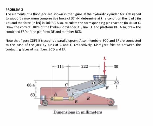
PROBLEM 2 The elements of a floor jack are shown in the figure. If the hydraulic cylinder AB is designed to support a maximum compressive force of 37 kN, determine at this condition the load L (in kN) and the force (in kN) in link EF. Also, calculate the corresponding pin reaction (in kN) at C. Draw the correct FBD's of the hydraulic cylinder AB, link EF and platform DF. Also, draw the combined FBD of the platform DF and member BCD. Note that figure CDFE if traced is a parallelogram. Also, members BCD and EF are connected to the base of the jack by pins at C and E, respectively. Disregard friction between the contacting faces of members BCD and EF. L 114 222 30 30 68.4 C 60 E B Dimensions in millimeters
PROBLEM 2 The elements of a floor jack are shown in the figure. If the hydraulic cylinder AB is designed to support a maximum compressive force of 37 kN, determine at this condition the load L (in kN) and the force (in kN) in link EF. Also, calculate the corresponding pin reaction (in kN) at C. Draw the correct FBD's of the hydraulic cylinder AB, link EF and platform DF. Also, draw the combined FBD of the platform DF and member BCD. Note that figure CDFE if traced is a parallelogram. Also, members BCD and EF are connected to the base of the jack by pins at C and E, respectively. Disregard friction between the contacting faces of members BCD and EF. L 114 222 30 30 68.4 C 60 E B Dimensions in millimeters
College Physics
1st Edition
ISBN:9781938168000
Author:Paul Peter Urone, Roger Hinrichs
Publisher:Paul Peter Urone, Roger Hinrichs
Chapter11: Fluid Statics
Section: Chapter Questions
Problem 83PE: The hydraulic system of a backhoe is used to lift a load as shown in Figure 11.45. (a) Calculate the...
Related questions
Question

Transcribed Image Text:PROBLEM 2
The elements of a floor jack are shown in the figure. If the hydraulic cylinder AB is designed
to support a maximum compressive force of 37 kN, determine at this condition the load L (in
kN) and the force (in kN) in link EF. Also, calculate the corresponding pin reaction (in kN) at C.
Draw the correct FBD's of the hydraulic cylinder AB, link EF and platform DF. Also, draw the
combined FBD of the platform DF and member BCD.
Note that figure CDFE if traced is a parallelogram. Also, members BCD and EF are connected
to the base of the jack by pins at C and E, respectively. Disregard friction between the
contacting faces of members BCD and EF.
L
114
222
30
30
68.4
60
E
B
Dimensions in millimeters
Expert Solution
This question has been solved!
Explore an expertly crafted, step-by-step solution for a thorough understanding of key concepts.
Step by step
Solved in 2 steps with 1 images

Knowledge Booster
Learn more about
Need a deep-dive on the concept behind this application? Look no further. Learn more about this topic, physics and related others by exploring similar questions and additional content below.Recommended textbooks for you

College Physics
Physics
ISBN:
9781938168000
Author:
Paul Peter Urone, Roger Hinrichs
Publisher:
OpenStax College

University Physics Volume 1
Physics
ISBN:
9781938168277
Author:
William Moebs, Samuel J. Ling, Jeff Sanny
Publisher:
OpenStax - Rice University

Physics for Scientists and Engineers: Foundations…
Physics
ISBN:
9781133939146
Author:
Katz, Debora M.
Publisher:
Cengage Learning

College Physics
Physics
ISBN:
9781938168000
Author:
Paul Peter Urone, Roger Hinrichs
Publisher:
OpenStax College

University Physics Volume 1
Physics
ISBN:
9781938168277
Author:
William Moebs, Samuel J. Ling, Jeff Sanny
Publisher:
OpenStax - Rice University

Physics for Scientists and Engineers: Foundations…
Physics
ISBN:
9781133939146
Author:
Katz, Debora M.
Publisher:
Cengage Learning