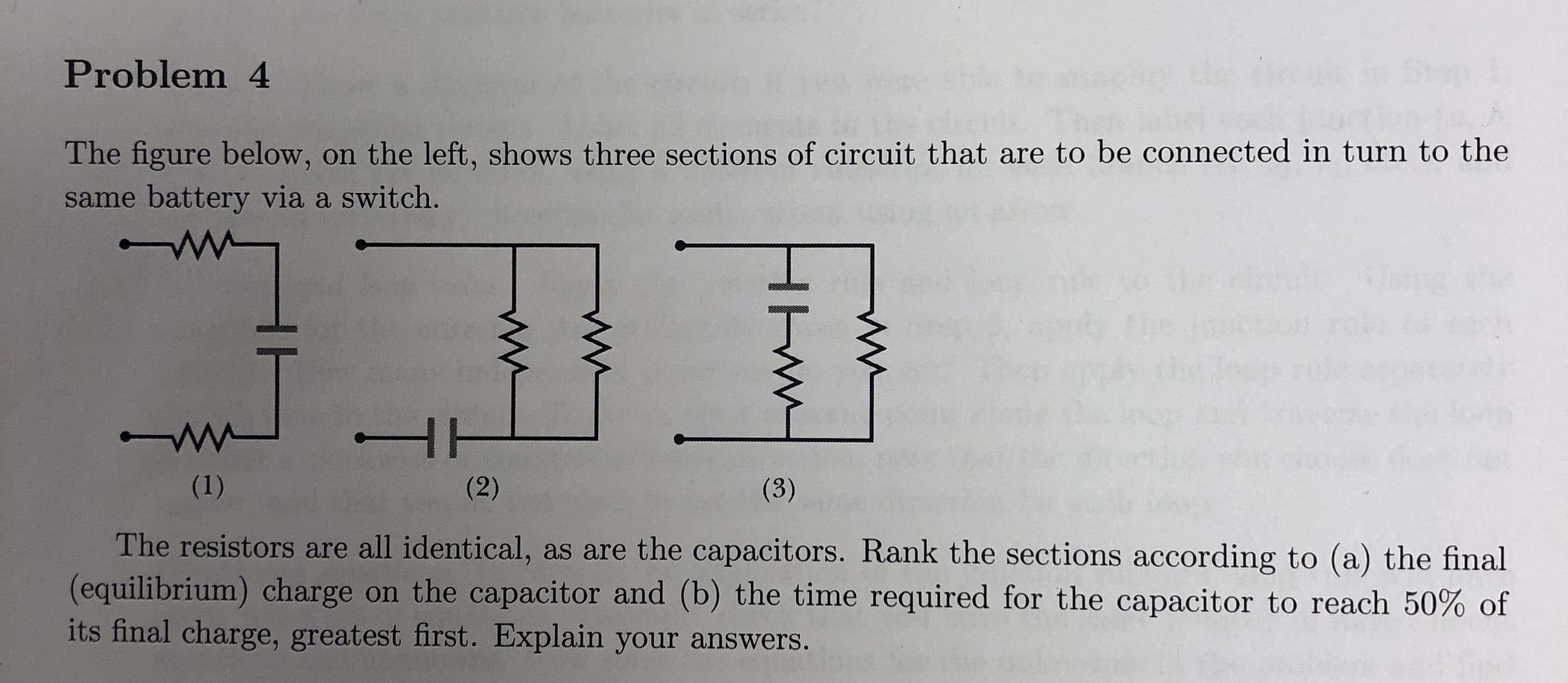
Problem 4 The figure below, on the left, shows three sections of circuit that are to be connected in turn to the same battery via a switch. The resistors are all identical, as are the capacitors. Rank the sections according to (a) the final (equilibrium) charge on the capacitor and (b) the time required for the capacitor to reach 50% of its final charge, greatest first. Explain your answers
Q: PROBLEM 5: In the circuit shown, Determine the following: A. Magnitude and direction of the current…
A:
Q: Consider the circuit shown in the figure(Figure 1). Suppose the four resistors in this circuit have…
A: I1=εR1+Req I1=1811+4.64=1.15 A
Q: Refer to the values in the box for the circuit shown in Figure. You can assume an ideal battery…
A:
Q: Part A The circuit shown below in (Figure 1) consists of four different resistors and a battery. You…
A:
Q: SOLVE FOR FIGURE B (Open Circuit) and PLEASE EXPLAIN HOW YOU GET IT. Note: There is a voltmeter so…
A: As there is an ideal voltmeter in a circuit hence there will be no current flowing through the…
Q: PROBLEM 1: A combination of three resistors R1 , R and R3 in series is connected across a voltage…
A: Resistance in Series We know that, sum of the voltages across the three resistors is equal to the…
Q: Suppose that & = 25 V. (Figure 1) You may want to review (Pages 768 - 771) Part A What is the…
A:
Q: Find the equivalent resistance, the current supplied by the battery and the current through each…
A: Given: Voltage of battery, V = 7 V Resistance, R1 = 1 Ω Resistance, R2 = 6 Ω Resistance, R3 = 2 Ω
Q: Constants | Periodic Part A Determine the terminal voltage of each battery in the ligure (Figure 1)…
A:
Q: 7. Suppose the circuit shown in Example Problem 1 has these values: R = 255 N, R2 = 290 N, and AV, =…
A: As the resistance of resistor R1 is 255 ohm and the potential difference across R1 is 17 V, hence…
Q: 3. Compare the differences for capacitors in scries and parallel. Then compare the differences for…
A: Compare capacitors and resistors in series and parallel .
Q: Problem 7: Three resisters are used in a circuit, with resistances R1 = R, R2= 2R, and R3 = 3R,…
A: Given, R= 1.5 ohms Therefore, R1=R= 1.5ohms R2=2R=2*1.5= 3ohms R3=3R=3*1.5= 4.5ohms
Q: Problem 3: The resistors in the circuit shown each have a resistance of 600 Q. What is the…
A: Equivalent resistance= 600 ohm.
Q: Question 2 a). Three lamps A, B and C are connected in parallel to a 220Vsupply. If the lamps are…
A:
Q: Please Show all steps, thank you!
A: To find the voltages and current in the given circuit, equivalent resistance is required.First 1Ω…
Q: PROBLEM 3: Four resistors, R1 = 100 N, R2 = 250 N, R3 = 350 N and R4 = 200 N are connected such that…
A:
Q: Problem 3: A circuit made up of 6 resistors is shown in the figure, with resistances R1 = 25 Q, R2 =…
A: In the given circuit, We have to determine the equivalent resistance in the given circuit.
Q: Need D,E,F,G
A: Given: R1 = 16 ohm, R2 = 85 ohm, R3 = 81 ohm, R4 = 69 ohm, R5 = 34 ohm, and E…
Q: Problem 28.5B: Three 100-V resistors are connected as shown in Figure below. The voltage between the…
A:
Q: Problem 3: A circuit made up of 6 resistors is shown in the figure, with resistances R1 = 25 Q, R2 =…
A: Given that -- R1 = 2s Q, R2 = 450, R3 = 290, R4 = 54 9, R5 = 84 Q, and R6 = 31 Q. The total current…
Q: 3. Given three color coded resistors; R₁ (Black, Orange, Green, Gold), R₂(Grey, Black, Orange,…
A:
Q: & E R₁ www R₂ Parallel Series Connection Connection In the diagrams above, resistors R₁ and R₂ are…
A:
Q: A battery has some internal resistance. (i) Can the potential difference across the terminals of…
A: Recall VT=ε-irWhere VT =terminal potential difference.
Q: PROBLEM 3: Four resistors, R1 = 12 Q, R2 = 15 Q R3 = 10 Q and R4 = 8 Q are connected such that the…
A: The circuit diagram is shown as, Here, i is the total current, i1 is the current passes to…
Q: 3) The three resistors in the circuit shown at the right are connected with a 12 V battery. The…
A:
Q: The circuit contains four resistors and an ideal battery. a. What is the equivalent resistance of…
A:
Q: Constants In the United States the standard voltage in homes is 120 V. Therefore, a "60 W American…
A: Answer given data Potential difference in US = 120 V Power of bulb = 60 W We have to find the…
Q: Problem 5: A circuit consisting of 5 resistors is shown in the graph. Their resistances are R1 = 14…
A:
Q: Figure 2 (a) Two capacitors C¡ and C2 and two resistors are connected to a battery in an arrangement…
A:
Q: How can I get the solution to these problems? (Answers are given)
A: A. The schematic arrangement of the circuit elements is shown below:
Q: Description A circuit is constructed with five resistors and a battery as shown. The battery…
A:
Q: Problem 5 The figure below shows a circuit consisting of three ideal batteries and four resistors.…
A: (a)The current through each battery can be determined by applying Kichchoff\'s loop rule. The…
Q: I Review I Constants I Periodic Table The lightbulb in the circuit diagram of (Figure 1) has a…
A:
Q: Figure 2 below shows a capacitor of capacitance C is connected in series with battery of emf, E, a…
A: Given : Asked to answer the second part of a Emf of the battery = E Resistance of the resistor = R…
Q: The pedestrian crossing of Washington Road and Ivy Lane (near the Physics building a) needs a…
A:
Q: A 50.0-µF capacitor has an initial charge of 500.0 µC. 1) If a resistance of 60.0 2 is connected…
A:
Q: Problem: Four resistors 2002, 7002, 1000Q, and 1,2002 connected in PARALLEL. Find the equivalent…
A: The circuit diagram is shown below.
Q: PROBLEM 4: Whale and Kanmuro are two islands located in the Chimera archipelago. These two are…
A: a) The current at full capacity is,
Q: Problem 9: A bank of batteries, total emf ɛ = 4.5 V, is in a circuit with resistor R = 150 kQ,…
A:
Q: Example 3: A circuit consists of three identical light bulbs, each of resistance R, connected to a…
A:
Q: Application (/14) 1. The diagram below shows an electric circuit with three light bulbs and one dry…
A:
Q: PROBLEM 1: A combination of three resistors R,, R2 and R3 in series is connected across a voltage…
A:
Q: Problem 4: A circuit consisting of 5 resistors is shown in the graph. Their resistances are R,-16 Ω,…
A: (a) The resistances R2, R3, and R4 are in parallel. The equivalent resistance of the combination of…
Q: The compressor on an air conditioner draws 40.0A when it starts up. If the start-up time is 0.50s,…
A: Q= It
Q: The circuit in the drawing contains two resistors and two capacitors that are connected to a battery…
A: Here Time constant of circuit is given by τ=ReqCeqReq=4×24+2kΩReq=86=43kΩCeq=C1+C2=3+6=9μF
Trending now
This is a popular solution!
Step by step
Solved in 1 steps
- Consider a closed circuit in series that uses a 1000 micro F capacitor. I have drawn a figure below to illustrate this. How does using different resistors (like a 120 ohm & 620 ohm) change the time constant t ? How does this affect the time it takes for the capacitor to charge/discharge? Explain?Differential equation Please write your explanation and don't use the calculator. 2. When discharging a capacitor in an RC (resistor-capacitor) circuit, the charge Q varies according to the equation:????? +??= 0where R is resistance, C is the capacitance (both constants). Find a function for the charge stored inthe capacitor: (There’s no need to know anything about electronics or physics to do this problem. R and C are just constants—just do the math.)?(?) = __________________________________________________What is the equivalent resistance of a 100 kΩ resistor and a 140 kΩ resistor in parallel? I first don't how the diagram would look, nor the how to determine equivalent resistance.
- I need help with d,e,f Refer to the values in the box for the circuit shown in Figure. You can assume an ideal battery d.For each resistor, calculate the current through the resistor with Sclosed. e.For each resistor, does the current increase or decrease when S isclosed? Why? f.Calculate the power dissipated in each resistor with S closed andopen and show that the total matches the power generated by the emf. i posted a pic of work for a to c a.What is the potential difference, Vab, between points a and b when the switch S is open andb.What is the potential difference, Vab, betweenpoints a and b when S is closed?c.For each resistor, calculate the current through the resistor with SopenI need help finding the voltage across the 1500 ohm resistor and the current through the 3900 ohm resistor. Attached is a picture of the circuit.The circuit in the figure on the right shows a network of resistors connected in series and in parallel. (a) Determine the total resistance of the network. (b) What is the current through the 3.00-Ω?
- 1. for this circuit you need to show your work find the total resistance, total current, the current and voltage drop at each restior, and power disputed at resistor c 2. For the circuit Need to find the total resistance the total current, the current and total voltage drop at each restior. and power disputed at resitor BRefer to the circuit on the side. (a) Find the total resistance of the external circuit RT, considering an ohmmeter is connected at terminals 1 and 2. Refer to the figure on the side. (b) When an ideal battery of 10v is connected to terminals 1 and 2, what is the current passing through the 5 Ω resistor?Help please, Show your complete (step-by-step) analysis and solution, with the appropriate equations and/or diagrams. Thank youu! 1. Originally, a circuit contains four (4) identical resistors in parallel across a battery. If one resistor is removed, what happens to the value of total current, total resistance and total voltage? Express the new quantities in terms of the original quantities.
- Refer to the figure 2: a) find the equivalent resistance of the collection of resistors in the circuit. b) if the capacitor is initially uncharged how long does it take for the capacitor to reach 25% of its maximum, after the switch is closed?Use the exact values you enter to make later calculations. The figure below shows a battery connected to a circuit. The potential difference across the battery and the resistance of each resistor is given in the figure. (Assume R1 = 11.5 Ω, R2 = 1.30 Ω, and V = 6.50 V.) (I skipped a-c) (d) Using the result from part (c), what is the equivalent resistance (in Ω) of the entire circuit? in Ω (e) What is the current (in A) through the battery (equivalently, the conventional current that exits the positive terminal of the battery and enters the R2)? in A (f) What is the magnitude of the potential difference (in V) across R2? in VPlease answer these guide questions based on the table. What can you say about the current (I) values across each individual resistor? What happens to the measured voltage (V) across each individual resistor? Compare the theoretical and measured values for the resistances (R) of each individual resistor and the corresponding voltage (V) across them. Explain the differences between theoretical and measured values referred to above? Compare the voltage of Source 1 to the sum of V1 and V2. Explain. Compare the voltage of Source 2 to the sum of V4 and V5. Explain. *Write a conclusion: