Problem 4. The Warren truss loaded as shown in the figure supported by a roller at C and a hinge at G. By the method of sections, compute the force in the members BC, DF, and CE. 80 KN A 60 KN с D M 6m 6 m E B 100 KN 40 KN 6 m 6 m
Problem 4. The Warren truss loaded as shown in the figure supported by a roller at C and a hinge at G. By the method of sections, compute the force in the members BC, DF, and CE. 80 KN A 60 KN с D M 6m 6 m E B 100 KN 40 KN 6 m 6 m

Chapter9: Application Of Influence Lines
Section: Chapter Questions
Problem 11P

Related questions

Question
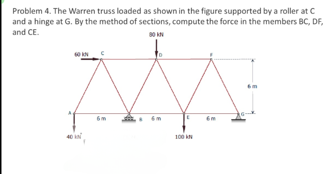
Transcribed Image Text:Problem 4. The Warren truss loaded as shown in the figure supported by a roller at C
and a hinge at G. By the method of sections, compute the force in the members BC, DF,
and CE.
80 KN
D
MA
E
6 m
B
A
60 KN с
40 kN
6m
100 kN
6m
6 m
Expert Solution
This question has been solved!
Explore an expertly crafted, step-by-step solution for a thorough understanding of key concepts.

Step by step
Solved in 5 steps with 5 images

Knowledge Booster


Learn more about
Need a deep-dive on the concept behind this application? Look no further. Learn more about this topic, civil-engineering and related others by exploring similar questions and additional content below.Recommended textbooks for you