Problem 5 In the given circuit the switch moves from position A to position B at time t = 0. Assuming that the circuit is in steady states before the switching operation c) What are the capacitor voltage and inductor current as a function of time for t> 0? 12Ω 60 12 0 5 H 16 0 A В t = 0 16 Ω 8 V 24 V 12 0 12Ω 0.05 F
Problem 5 In the given circuit the switch moves from position A to position B at time t = 0. Assuming that the circuit is in steady states before the switching operation c) What are the capacitor voltage and inductor current as a function of time for t> 0? 12Ω 60 12 0 5 H 16 0 A В t = 0 16 Ω 8 V 24 V 12 0 12Ω 0.05 F

Delmar's Standard Textbook Of Electricity
7th Edition
ISBN:9781337900348
Author:Stephen L. Herman
Publisher:Stephen L. Herman
Chapter21: Resistive-capacitive Series Circuits
Section: Chapter Questions
Problem 2PP: Assume that the voltage drop across the resistor, ER, is 78 V; the voltage drop across the...

Related questions
Question
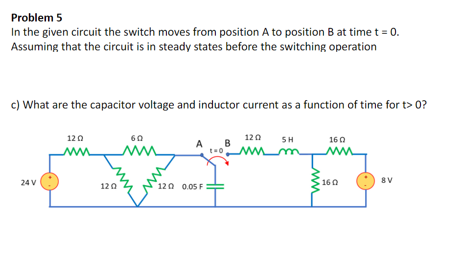
Transcribed Image Text:Problem 5
In the given circuit the switch moves from position A to position B at time t = 0.
Assuming that the circuit is in steady states before the switching operation
c) What are the capacitor voltage and inductor current as a function of time for t> 0?
12Ω
B
12 0
5 H
16 0
A
t= 0
ww
24 V
16 0
8 V
12 0
12 0 0.05 F
Expert Solution
This question has been solved!
Explore an expertly crafted, step-by-step solution for a thorough understanding of key concepts.

This is a popular solution!

Trending now
This is a popular solution!

Step by step
Solved in 5 steps with 5 images

Recommended textbooks for you
Delmar's Standard Textbook Of Electricity
Electrical Engineering
ISBN:
9781337900348
Author:
Stephen L. Herman
Publisher:
Cengage Learning
Delmar's Standard Textbook Of Electricity
Electrical Engineering
ISBN:
9781337900348
Author:
Stephen L. Herman
Publisher:
Cengage Learning