Problem 7. The 30-mm diameter shaft is subjected to the vertical and horizontal loadings of two pulleys as shown. It is supported on two journal bearings at A and B which offer no resistance to axial loading. Furthermore, the coupling to the motor at C can be assumed not to offer any support to the shaft. The shaft is subjected to both M₂ and My internal bending moment components. (a) Draw a bending moment diagram for each component. (b) Since all axes through the circle's center for circular shaft are principal axis, then the resultant M = √ √M²+ M² can be used to determine the maximum bending stress. Determine the location and y 150 N 1 m Z 150 N 1 m E 60 mm 1 m 100 mm B 1 m 400 N 400 N
Problem 7. The 30-mm diameter shaft is subjected to the vertical and horizontal loadings of two pulleys as shown. It is supported on two journal bearings at A and B which offer no resistance to axial loading. Furthermore, the coupling to the motor at C can be assumed not to offer any support to the shaft. The shaft is subjected to both M₂ and My internal bending moment components. (a) Draw a bending moment diagram for each component. (b) Since all axes through the circle's center for circular shaft are principal axis, then the resultant M = √ √M²+ M² can be used to determine the maximum bending stress. Determine the location and y 150 N 1 m Z 150 N 1 m E 60 mm 1 m 100 mm B 1 m 400 N 400 N

Mechanics of Materials (MindTap Course List)
9th Edition
ISBN:9781337093347
Author:Barry J. Goodno, James M. Gere
Publisher:Barry J. Goodno, James M. Gere
Chapter11: Columns
Section: Chapter Questions
Problem 11.2.4P: Repeat Problem 11.2-3 assuming that R= 10 kN · m/rad and L = 2 m.

Related questions

Question
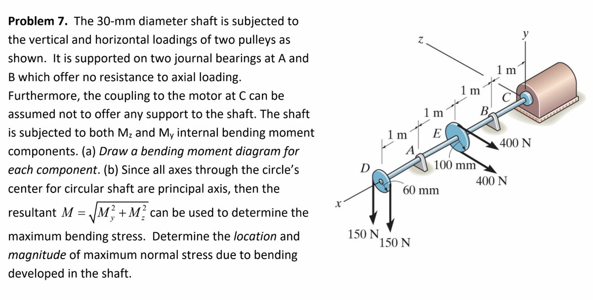
Transcribed Image Text:Problem 7. The 30-mm diameter shaft is subjected to
the vertical and horizontal loadings of two pulleys as
shown. It is supported on two journal bearings at A and
B which offer no resistance to axial loading.
Furthermore, the coupling to the motor at C can be
assumed not to offer any support to the shaft. The shaft
is subjected to both Mz and My internal bending moment
components. (a) Draw a bending moment diagram for
each component. (b) Since all axes through the circle's
center for circular shaft are principal axis, then the
resultant M = √M²+ M² can be used to determine the
y
maximum bending stress. Determine the location and
magnitude of maximum normal stress due to bending
developed in the shaft.
X
150 N
1 m
2
150 N
1 m
E
60 mm
1 m
100 mm
1 m
400 N
400 N
Expert Solution
This question has been solved!
Explore an expertly crafted, step-by-step solution for a thorough understanding of key concepts.

This is a popular solution!

Trending now
This is a popular solution!

Step by step
Solved in 4 steps with 4 images

Knowledge Booster


Learn more about
Need a deep-dive on the concept behind this application? Look no further. Learn more about this topic, mechanical-engineering and related others by exploring similar questions and additional content below.Recommended textbooks for you
Mechanics of Materials (MindTap Course List)
Mechanical Engineering
ISBN:
9781337093347
Author:
Barry J. Goodno, James M. Gere
Publisher:
Cengage Learning
Mechanics of Materials (MindTap Course List)
Mechanical Engineering
ISBN:
9781337093347
Author:
Barry J. Goodno, James M. Gere
Publisher:
Cengage Learning