Problem 7.88 Figure -1.5 m 6 kN/m 1.5 m 1 of 1 > 3 kN B Part A Draw the shear diagram for the beam. Follow the sign convention. (Figure 1) Click on "add vertical line off" to add discontinuity lines. Then click on "add segment" button to add functions between the lines. Note - The curve you choose from the drop-down is only a pictorial representation of a real quadratic/cubic curve. The equation of this curve is not mathematically equivalent to the correct answer. Consequently, slopes at discontinuities and intercepts with the x-axis (if any) are not accurate. +0 No elements selected Part B No elements selected 20 Add discontinuity lines and select segments to add to the canvas. 15 10 5 0 A M(Nm) 25 -5 VAN) -15 120 -10- -20 -25 8 Draw the moment diagram for the beam. Follow the sign convention. Click on "add vertical line off" to add discontinuity lines. Then click on "add segment" button to add functions between the lines. Note - The curve you choose from the drop-down is only a pictorial representation of a real quadratic/cubic curve. The equation of this curve is not mathematically equivalent to the correct answer. Consequently, slopes at discontinuities and intercepts with the x-axis (if any) are not accurate. Û 0 -8 -12- 0 1.5 m Add discontinuity lines and select segments to add to the canvas. 6 kN/m -1.5 m 6 kN/m 1.5 m 3 2 3 kN 1.5 m 3 kN B B x(m) (3) x(m)
Problem 7.88 Figure -1.5 m 6 kN/m 1.5 m 1 of 1 > 3 kN B Part A Draw the shear diagram for the beam. Follow the sign convention. (Figure 1) Click on "add vertical line off" to add discontinuity lines. Then click on "add segment" button to add functions between the lines. Note - The curve you choose from the drop-down is only a pictorial representation of a real quadratic/cubic curve. The equation of this curve is not mathematically equivalent to the correct answer. Consequently, slopes at discontinuities and intercepts with the x-axis (if any) are not accurate. +0 No elements selected Part B No elements selected 20 Add discontinuity lines and select segments to add to the canvas. 15 10 5 0 A M(Nm) 25 -5 VAN) -15 120 -10- -20 -25 8 Draw the moment diagram for the beam. Follow the sign convention. Click on "add vertical line off" to add discontinuity lines. Then click on "add segment" button to add functions between the lines. Note - The curve you choose from the drop-down is only a pictorial representation of a real quadratic/cubic curve. The equation of this curve is not mathematically equivalent to the correct answer. Consequently, slopes at discontinuities and intercepts with the x-axis (if any) are not accurate. Û 0 -8 -12- 0 1.5 m Add discontinuity lines and select segments to add to the canvas. 6 kN/m -1.5 m 6 kN/m 1.5 m 3 2 3 kN 1.5 m 3 kN B B x(m) (3) x(m)

Mechanics of Materials (MindTap Course List)
9th Edition
ISBN:9781337093347
Author:Barry J. Goodno, James M. Gere
Publisher:Barry J. Goodno, James M. Gere
Chapter9: Deflections Of Beams
Section: Chapter Questions
Problem 9.7.12P: A simple beam ACE is constructed with square cross sections and a double taper (see figure). The...

Related questions
Question
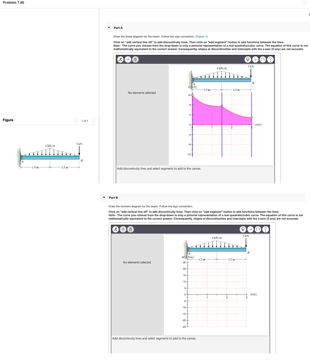
Draw shear and moment diagram. Assuming x=0 from A side to x= 3 at B .
( explain in details)
Transcribed Image Text:Problem 7.88
Figure
-1.5 m
6 kN/m
1.5 m
1 of 1 >
3 kN
B
Part A
Draw the shear diagram for the beam. Follow the sign convention. (Figure 1)
Click on "add vertical line off" to add discontinuity lines. Then click on "add segment" button to add functions between the lines.
Note - The curve you choose from the drop-down is only a pictorial representation of a real quadratic/cubic curve. The equation of this curve is not
mathematically equivalent to the correct answer. Consequently, slopes at discontinuities and intercepts with the x-axis (if any) are not accurate.
+0
No elements selected
Part B
No elements selected
20
Add discontinuity lines and select segments to add to the canvas.
15
10
5
0
A
M(Nm)
25
-5
VAN)
-15
120
-10-
-20
-25
8
Draw the moment diagram for the beam. Follow the sign convention.
Click on "add vertical line off" to add discontinuity lines. Then click on "add segment" button to add functions between the lines.
Note - The curve you choose from the drop-down is only a pictorial representation of a real quadratic/cubic curve. The equation of this curve is not
mathematically equivalent to the correct answer. Consequently, slopes at discontinuities and intercepts with the x-axis (if any) are not accurate.
Û
0
-8
-12-
0
1.5 m
Add discontinuity lines and select segments to add to the canvas.
6 kN/m
-1.5 m
6 kN/m
1.5 m
3
2
3 kN
1.5 m
3 kN
B
B
x(m)
(3)
x(m)
Expert Solution
This question has been solved!
Explore an expertly crafted, step-by-step solution for a thorough understanding of key concepts.

This is a popular solution!

Trending now
This is a popular solution!

Step by step
Solved in 5 steps with 5 images

Knowledge Booster


Learn more about
Need a deep-dive on the concept behind this application? Look no further. Learn more about this topic, mechanical-engineering and related others by exploring similar questions and additional content below.Recommended textbooks for you
Mechanics of Materials (MindTap Course List)
Mechanical Engineering
ISBN:
9781337093347
Author:
Barry J. Goodno, James M. Gere
Publisher:
Cengage Learning
Mechanics of Materials (MindTap Course List)
Mechanical Engineering
ISBN:
9781337093347
Author:
Barry J. Goodno, James M. Gere
Publisher:
Cengage Learning