Problem: A 250 resistor is connected inductance in parallel with an of 2.5 mH across a Vrms = 75<0° V, f = 1 kHz supply. Calculate (a) the current in each branch, (b) the supply current, (c) the circuit phase angle, (d) the circuit impedance and (e) the power consumed.
Problem: A 250 resistor is connected inductance in parallel with an of 2.5 mH across a Vrms = 75<0° V, f = 1 kHz supply. Calculate (a) the current in each branch, (b) the supply current, (c) the circuit phase angle, (d) the circuit impedance and (e) the power consumed.

Delmar's Standard Textbook Of Electricity
7th Edition
ISBN:9781337900348
Author:Stephen L. Herman
Publisher:Stephen L. Herman
Chapter17: Resistive-inductive Series Circuits
Section: Chapter Questions
Problem 2PA: You are a journeyman electrician working in an industrial plant. Your task is to connect an inductor...

Related questions
Question
2.. please choose the correct answer and show your complete solution
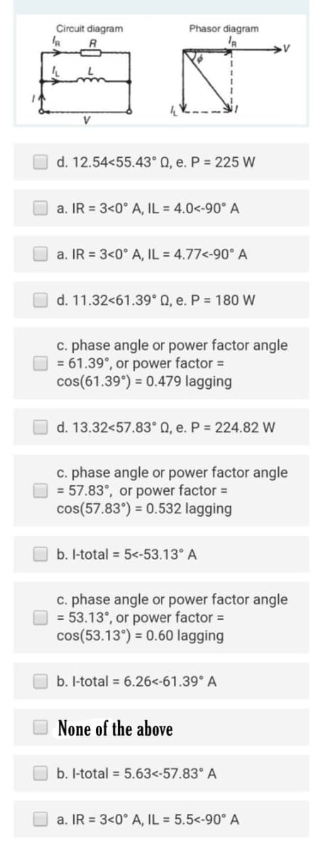
Transcribed Image Text:Circuit diagram
V
Phasor diagram
IR
d. 12.54<55.43° Q, e. P = 225 W
a. IR = 3<0° A, IL = 4.0<-90° A
a. IR = 3<0° A, IL = 4.77<-90° A
d. 11.32<61.39° Q, e. P = 180 W
c. phase angle or power factor angle
= 61.39°, or power factor =
cos(61.39°) = 0.479 lagging
d. 13.32<57.83° Q, e. P = 224.82 W
c. phase angle or power factor angle
= 57.83°, or power factor =
cos (57.83°) = 0.532 lagging
b. l-total = 5<-53.13° A
c. phase angle or power factor angle
= 53.13°, or power factor =
cos(53.13°) = 0.60 lagging
b. l-total = 6.26<-61.39° A
None of the above
b. l-total = 5.63<-57.83° A
a. IR 3<0° A, IL = 5.5<-90° A
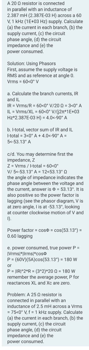
Transcribed Image Text:A 20 Q resistor is connected
in parallel with an inductance of
2.387 mH (2.387E-03 H) across a 60
V, 1 kHz (1E+03 Hz) supply. Calculate
(a) the current in each branch, (b) the
supply current, (c) the circuit
phase angle, (d) the circuit
impedance and (e) the
power consumed.
Solution: Using Phasors
First, assume the supply voltage is
RMS and as reference at angle 0.
Vrms = 60<0° V
a. Calculate the branch currents, IR
and IL
IR = Vrms/R = 60<0° V/20 Q = 3<0° A
IL = Vrms/XL = 60<0° V/(2*1E+03
Hz*2.387E-03 H) = 4.0<-90° A
b. l-total, vector sum of IR and IL
I-total = 3<0° A + 4.0<-90° A =
5<-53.13° A
c/d. You may determine first the
impedance, Z
Z = Vrms / I-total = 60<0°
V/ 5<-53.13° A = 12<53.13° 0
the angle of impedance indicates the
phase angle between the voltage and
the current, answer is = 53.13°. It is
also positive so the power factor is
lagging (see the phasor diagram, V is
at zero angle, I is at -53.13°, looking
at counter clockwise motion of V and
1).
Power factor = cos = cos(53.13°) =
0.60 lagging
e. power consumed, true power P =
|Vrms|*|Irms|*cos
P = (60V)(5A)cos(53.13°) = 180 W
or
P = |IR|^2*R = (3^2) *20 Q = 180 W
remember the average power, P for
reactances XL and Xc are zero.
Problem: A 25 Q resistor is
connected in parallel with an
inductance of 2.5 mH across a Vrms
= 75<0° V, f = 1 kHz supply. Calculate
(a) the current in each branch, (b) the
supply current, (c) the circuit
phase angle, (d) the circuit
impedance and (e) the
power consumed.
Expert Solution
This question has been solved!
Explore an expertly crafted, step-by-step solution for a thorough understanding of key concepts.

Step by step
Solved in 4 steps with 4 images

Recommended textbooks for you
Delmar's Standard Textbook Of Electricity
Electrical Engineering
ISBN:
9781337900348
Author:
Stephen L. Herman
Publisher:
Cengage Learning
Delmar's Standard Textbook Of Electricity
Electrical Engineering
ISBN:
9781337900348
Author:
Stephen L. Herman
Publisher:
Cengage Learning