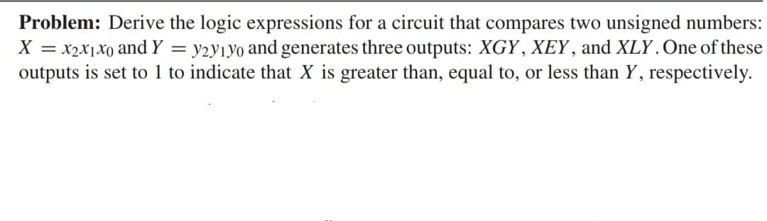
Problem: Derive the logic expressions for a circuit that compares two unsigned numbers: X = x2x₁x0 and Y = y2y1yo and generates three outputs: XGY, XEY, and XLY. One of these outputs is set to 1 to indicate that X is greater than, equal to, or less than Y, respectively.


Q: 8. In 8-bit microprocessor, how many opcodes are present?
A: The correct option along with the explanation is provided in the following section.
Q: 19. What is the minimum distance required for single error detection according to Hamming's analysis…
A: The solution is provided in the following section.
Q: The switch in the circuit in Fig. P7.1 has been closed for a long time before opening at t = 0. a)…
A: We are authorized to answer only 3 subparts at a time since you have not mentioned which part you…
Q: Question 1 A 125 MVA, 20 kV, three-phase, wye-connected, 60 Hz, synchronous alternator is connected…
A: From the given data,to find the given answers to questions given = ?
Q: An electric power plant can produce electricity at a fixed power P, but the plant operator is free…
A: (a) Power lost= I2×R where, I= current through transmission line R= total resistance of transmission…
Q: Q3:-Using superposition, determine the current through the (6 2) resistor for network of Fig.2. 82…
A:
Q: D13.5. Determine the wave angles 0m for the first four modes (m= 1, 2, 3, n a parallel-plate guide…
A: Solution- Given, d = 2 cm ∈r' = 1 f = 30 GHz βx2+βz2 =β2=ω2μ∈βz =βsinθm, βx=βcosθm To solve…
Q: a) V1: c) V3: c) IT: V1 b) V2: d) RT:
A:
Q: x(t) = δ(t
A:
Q: a shunt motor, the permanent magnet is replaced by an electromagnet activated by a field coil that…
A: Given, Dc shunt motor, Armature resistance = 0.05 ohms , Terminal/Supply voltage = 120 volts. We…
Q: A temperature-to-voltage Input (°C) x 40 converter is designed to work in the following way: Output…
A:
Q: Discuss in detail the motor that are commonly employed for electric vehicular application
A: Below are the types of motor used in electrical vehicles: Electrical vehicles will rules the…
Q: V Figure Link R₁ R3 R₂ ww 9 V If R₁ = 4 02, R2 = 22, and R3 = 2 Ω, calculate Ix (in amperes) in the…
A: For the given electrical circuit we need to calculate the value of current Ix.
Q: A loss-less 200N line is terminated on a load given by (200-j200)№. Given that the propagation…
A: the Given loss-less 200Ω line is terminated on a load 200-j200Ω The Propagation constant is…
Q: he output signal from a frequency inverter will appear on a scope screen as a: A. pure sine wave of…
A: Frequency inverter : Every inverter has a base frequency of 50 to 60 Hz a control method is used to…
Q: 5. Find x[n] for each DTFT given below: (a) Xa(w) = 1+e-jw3 (b) Xa(w) = e-jw1.5, (c) Xa(w) =…
A:
Q: The magnetic structure shown in the figure is built with a material whose magnetization curve is…
A:
Q: A coil of resistance 200 and inductance 10 mH is in series with a capacitance and is supplied with a…
A: Given, A coil with series RLC circuit having, Resistance, R = 20 Ω Inductance, L = 10 mH The maximum…
Q: A 3 HWCR has a supply of 110V / phase. Find out the value of mean voltage for a delay angle of 150°…
A:
Q: 5. Use the concept of node voltage analysis to find io in the circuit shown: 16V +1 8Ω ww 5Ω 8 Ω Μ…
A: Given circuit:
Q: Question 6 A 470 ohm resistor has 18.8 volts across it. What is the power consumed by that resistor?…
A: Given, Resistance, R = 470 ohm Voltage across resistor, V = 18.8 V
Q: A line is 20 cm long and at 1 GHz the phase constant β is 20 rad/m. What is the electrical length of…
A: Given data, Length l=20 cm = 0.2 m Phase constant β=20 rad/m
Q: R(s) G₁(s) G₂(s) G4(S) G3(s) G5(s) G6(s) -H₁(s) G7(s) ) Find the equivalent transfer function of…
A:
Q: Derive the transfer function H(s) = Vo(s)/Vi(s) for the circuit shown. (Hint: consider finding V+/Vi…
A: The given circuit is,
Q: The 60 mile, 115 kV line GH (Figure P12.8) is operating with the voltages at each end 30° out of…
A: Given, A line GH is operating with the voltages at each end 30° out of phase is shown below,
Q: Write short notes on the following: i) Current transformers ii) Potential transformers…
A: Potential Transformer: A potential…
Q: 4. Use Thevenin's theorem to find the current flowing in the 82 resistor for the circuit shown in…
A: Given data : The given circuit is shown below,
Q: A charge q = 4.11 * 10-9 C is placed at the origin, x = 0, and a second charge equal to -2q is…
A: Given: q=4.11×10⁻⁹ C at x=0-2q=-8.22×10⁻⁹ C at x=1 m
Q: what is circuit breker ? function
A: Given: what is a circuit breaker? Required: Function of the circuit breaker
Q: Find the time-domain expression corresponding to each phasor: a. V = 18.6/-54°V. b. I (20/45° -…
A:
Q: An unwanted component in a signal can be filtered out using a digital filter. A Discrete V input…
A: According to the question, (1) Design a high pass FIR digital filter. Note: Part (b) of the question…
Q: Find the F.T. of the fall wing Signals (functions) * (t) = 1 + cos (6πt + I)
A: Calculation of Fourier transform of following function : ft=1+cos6πt+π8 we…
Q: Using mesh analysis determine mesh current i and the value of k which causes i=0, if V₁ = 10 V and…
A:
Q: If two capacitors having capacitance of 5 µF and 10 µF respectively are connected in series across a…
A: Given, Two capacitors of 5 μF and 10 μF are connected in series across supply voltage 200 V. C1=5…
Q: (a) (b) x(t) = 20cos(4πt + 0.1) Calculate the Nyquist frequency of the given signal Based on the…
A:
Q: A coaxial cable has an inner conductor of radius a, and outer thin cylindrical shell of radius b. A…
A: Ampere’s law is used to determine the magnetic field due current carrying conductor. It states that…
Q: What do you understand by multi quadrant operation in an Electric drive? What are the advantages of…
A: Types of quadrant operation in Electric Drive Forward Motoring Reverse Motoring Forward Braking…
Q: A series RLC circuit is connected to a 400-hZ line with an applied voltage of 35.678 V. The resistor…
A: A resistor 'R', an inductor 'L', and a capacitor 'C' coupled either in series or parallel make up an…
Q: 5) An air conditioner operates at 240 Vrms at a frequency of 60 Hz. It absorbs an average power of 9…
A:
Q: Two reactors are connected in series across a 10 V, 10 kHz source. They are spaced so that there is…
A:
Q: a. VGS b. ID c. VD d. VS
A: Given:
Q: Short discuss about transformer cooling...
A: Transformer:- A device that moves electric energy from one alternating-current circuit to one other…
Q: Find the F.T. of the fall wing Signals (functions) e(t) = 3 5gh(3+) - Ast +jt ans: F(W) = 4/3 J 30…
A:
Q: An amplifier is connected to a load by a trans mission line matched to the amplifier. If the SWIF on…
A: Given: SWR=1.5 Required: Percentage of the available power absorbed by the load,
Q: System based on the parameters. 3. (a) Determine the range of values of k for system to be stable…
A: The characteristic equation is given as-s4+22s3+10s2+s+K=0 Applying R-H criteria gives, s4 1 10…
Q: For the two-port network below, calculate the value V₂, given 1₁ = 0.052 A and 12 = 0.005 A. I₁ V₁ =…
A:
Q: Answer the following Questions referring the circuit in figure 10. ID E-8V + VD- ✈ Si IR R2.2 k2 VR
A: Given,
Q: For the two-port network below, calculate the value V₂, given 1₁ = 0.052 A and 12 = 0.005 A. 1₂ I₁…
A: Given, A two port network, I1=0.052 AI2=0.005 A
Q: A capacitor takes a charge of 0.05 coulomb when connected across a 250 V source. Determine the…
A:
Q: A 500 W lamp having MSCP of 800 is suspended 3 m . above the working plane, Determine i)…
A:

Step by step
Solved in 2 steps with 2 images


- Design a 4-bit arithmetic circuit, with two selection variables S1 and S0, that generates the arithmetic operations in the following table. Draw the logic diagram for a single bit stage. Note that B’ represents “Not B”. Draw the logic diagram for a single bit stagA combinational logic circuit that compares between two 2-bit numbers A (A1 A0) and B(B1 B0) is designed. Output F is high when ? > ? and low when ? < ?. 1) Are there any undefined outputs? If there are any undefined outputs what are the inputs?Determine the simplified Sum of Product expression of Q1 and Q2 from the table using a K-Map, then draw the simplified logic diagram. SHOW KMAP WITH THE FINAL EXPRESSION & LOGIC DIAGRAM
- (1) Find out the logic expression of output Q for the circuit on the left. And prove this is equivalent to the D latch circuit on the right. (2) Explain which is better and why?Using the analysis technique where you first extract the truth table and then use it to derive the output’s logic expression, analyze the circuit. Record your results below. I added the circuit as an image Conclusion In your own words, describe the process used to analyze a logic circuit where you first extract a truth table and then derive the logic expression. 2.Again, in your own words, describe the process used to analyze a logic circuit where you first extract the logic expression and then derive the truth table.Examine the circuit given below. Write the expression for outputs Q1, Q2, and Q. Clearly indicate which logic gate Q output is using Boolean Algebra and write the name of this logic gate.
- 1. Given the Boolean expression (b + d)(a’+ b’ + c),a. Convert the expression to the other standard form. What do you call this standard form?b. Derive its canonical form. What do you call this canonical form?c. Derive the other canonical form. What do you call this canonical form?d. Provide the truth table of the expressione. Draw the logic circuit diagrams of the 2 standard formsA circuit which takes a binary-coded decimal (BCD) number as input s to be designed such that the single output Q is true if the input is a prime number (remerber that 0 and 1 count as prime numbers). (a)Draw a truth table that specifies the above circuit (b)Using the truth table you have constructed and the Karnaugh map method find the minimised Boolean expression for the output Q. (c)Implement the digital circuit using the minimum number of 2-input logic AND, OR gates and inverters (NOT.1-Using the Karnaugh Method, design and draw the circuit of the logic circuit that gives the result of the multiplication of the two-bit numbers "AB" and "CD" according to minterms (SOP). Do not make any further simplifications before or after the Karnaugh Method. In tables and Karnaugh, ensure that the least significant bit is on the far right and the entries are sorted alphabetically. Make sure that the circuit you have drawn is understandable, the function you have written and the truth table are readable.
- Using a 4-bit signed input P=P3P2P1P0 and a control input Z, use a 4-bit adder and any logicgates to design a digital circuit that does the following: ● Outputs P + 3, if the input Z = 0● Outputs P − 3, if the input Z = 1 You can ignore cases where an overflow* might occur after performing the addition or subtraction operation, as long as the circuit performs the signed binary arithmetic correctly. *In computers, typically there is additional circuitry for an overflow flag that gets triggered when the result of an arithmetic operation “does not fit” the number of bits allocated for the output. Please ensure that your components, such as your 4-bit adder are shown clearly with the complete labels of their input and output pins and signals. The sample diagram below shows examples of these labels.is it possible to connect the outputs of a comparator to a logic gate (connected to an led)? The led connected to the logic gate lights up if the inputs of the comparator both satisfy a condition, for example, the voltage of both inputs are less than the reference voltages.DIGITAL LOGICGiven the two binary numbers X = 1000100 and Y = 100101 , perform the subtraction X - Y by using 1's complement and 2's complement.