Problem set 1 Compute the line voltages and currents of the load. Load Side: a 0,1 0 j0.2 Ω Α 10 Ω j5n Line Currents 'A =1 0,1 0 jo.2 N B 12 N j4 N 208-240° V rms 'c- -12 108-120° V rms Line voltages VAB = VBC VCA = 0.1 0 jo.2 N 12Ω j4 N C I+
Problem set 1 Compute the line voltages and currents of the load. Load Side: a 0,1 0 j0.2 Ω Α 10 Ω j5n Line Currents 'A =1 0,1 0 jo.2 N B 12 N j4 N 208-240° V rms 'c- -12 108-120° V rms Line voltages VAB = VBC VCA = 0.1 0 jo.2 N 12Ω j4 N C I+

Power System Analysis and Design (MindTap Course List)
6th Edition
ISBN:9781305632134
Author:J. Duncan Glover, Thomas Overbye, Mulukutla S. Sarma
Publisher:J. Duncan Glover, Thomas Overbye, Mulukutla S. Sarma
Chapter2: Fundamentals
Section: Chapter Questions
Problem 2.30P: Figure 2.26 shows three loads connected in parallel across a 1000-V(RMS),60Hz single-phase source....

Related questions
Question
Use mesh current analysis to solve the unbalanced system.
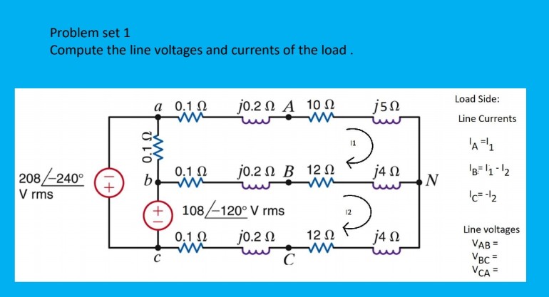
Transcribed Image Text:Problem set 1
Compute the line voltages and currents of the load.
Load Side:
а 0,10
j0.2 Ω Α 10 Ω
j5n
Line Currents
'A=1
0,1 N
jo.2 N B 12 N
j4 N
'B=1-12
208-240°
V rms
108-120° V rms
Line voltages
VAB =
VBC =
VCA =
0.1 0
jo.2 N
12 0
j4 N
C
Expert Solution
This question has been solved!
Explore an expertly crafted, step-by-step solution for a thorough understanding of key concepts.

Step by step
Solved in 2 steps with 2 images

Knowledge Booster


Learn more about
Need a deep-dive on the concept behind this application? Look no further. Learn more about this topic, electrical-engineering and related others by exploring similar questions and additional content below.Recommended textbooks for you
Power System Analysis and Design (MindTap Course …
Electrical Engineering
ISBN:
9781305632134
Author:
J. Duncan Glover, Thomas Overbye, Mulukutla S. Sarma
Publisher:
Cengage Learning
Power System Analysis and Design (MindTap Course …
Electrical Engineering
ISBN:
9781305632134
Author:
J. Duncan Glover, Thomas Overbye, Mulukutla S. Sarma
Publisher:
Cengage Learning