Problem The cross section and dimensions of a 8 m long asymmetric I-beam are shown in Figure 1. Determine: (a) The position of the neutral-axis(centroid) relative to the bottom face edge. (b) The second moment of area about the neutral axis. If the beam is in a simply supported arrangement (Figure 2) and if the maximum allowable bending stress in the beam is 180 MPa, determine: (c) The maximum allowable point load, W applied at the center of the beam L-8 m 350 450 009 Figure 1: Beam cross-section view (All dimensions in mm) Figure 2: Side view - Simply supported beam
Problem The cross section and dimensions of a 8 m long asymmetric I-beam are shown in Figure 1. Determine: (a) The position of the neutral-axis(centroid) relative to the bottom face edge. (b) The second moment of area about the neutral axis. If the beam is in a simply supported arrangement (Figure 2) and if the maximum allowable bending stress in the beam is 180 MPa, determine: (c) The maximum allowable point load, W applied at the center of the beam L-8 m 350 450 009 Figure 1: Beam cross-section view (All dimensions in mm) Figure 2: Side view - Simply supported beam

Mechanics of Materials (MindTap Course List)
9th Edition
ISBN:9781337093347
Author:Barry J. Goodno, James M. Gere
Publisher:Barry J. Goodno, James M. Gere
Chapter9: Deflections Of Beams
Section: Chapter Questions
Problem 9.10.5P: A weight W = 4000 lb falls through a height h = 0.5 in, onto the midpoint of a simple beam of length...

Related questions

Question
Hight =600
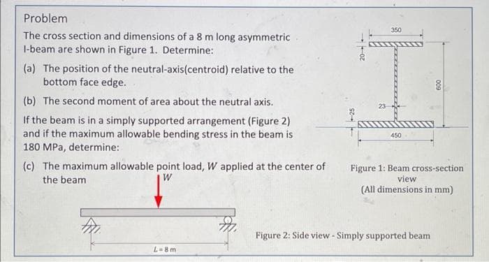
Transcribed Image Text:Problem
The cross section and dimensions of a 8 m long asymmetric
I-beam are shown in Figure 1. Determine:
(a) The position of the neutral-axis (centroid) relative to the
bottom face edge.
(b) The second moment of area about the neutral axis.
If the beam is in a simply supported arrangement (Figure 2)
and if the maximum allowable bending stress in the beam is
180 MPa, determine:
(c) The maximum allowable point load, W applied at the center of
the beam
W
L=8m
20-
I
23
350
450
009
Figure 1: Beam cross-section
view
(All dimensions in mm)
Figure 2: Side view - Simply supported beam
Expert Solution
This question has been solved!
Explore an expertly crafted, step-by-step solution for a thorough understanding of key concepts.

Step by step
Solved in 5 steps with 5 images

Knowledge Booster


Learn more about
Need a deep-dive on the concept behind this application? Look no further. Learn more about this topic, mechanical-engineering and related others by exploring similar questions and additional content below.Recommended textbooks for you
Mechanics of Materials (MindTap Course List)
Mechanical Engineering
ISBN:
9781337093347
Author:
Barry J. Goodno, James M. Gere
Publisher:
Cengage Learning
Mechanics of Materials (MindTap Course List)
Mechanical Engineering
ISBN:
9781337093347
Author:
Barry J. Goodno, James M. Gere
Publisher:
Cengage Learning