pute the phasors I,, I, and V. (b) Draw a phasor diagram showing I, I,, I, and V.
pute the phasors I,, I, and V. (b) Draw a phasor diagram showing I, I,, I, and V.

Power System Analysis and Design (MindTap Course List)
6th Edition
ISBN:9781305632134
Author:J. Duncan Glover, Thomas Overbye, Mulukutla S. Sarma
Publisher:J. Duncan Glover, Thomas Overbye, Mulukutla S. Sarma
Chapter2: Fundamentals
Section: Chapter Questions
Problem 2.31P: Consider two interconnected voltage sources connected by a line of impedance Z=jX, as shown in...

Related questions

Question
For the single-phase circuit shown in Figure 2.22, I5 10/08A. (a) Compute the phasors I1, I2, and V. (b) Draw a phasor diagram showing I, I1 I2, and V
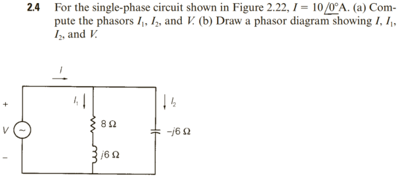
Transcribed Image Text:2.4 For the single-phase circuit shown in Figure 2.22, I = 10/0°A. (a) Com-
pute the phasors I,, I, and V. (b) Draw a phasor diagram showing I, I,
I, and V.
%3D
-j6 N
j6 2
-1
Expert Solution
This question has been solved!
Explore an expertly crafted, step-by-step solution for a thorough understanding of key concepts.

This is a popular solution!

Trending now
This is a popular solution!

Step by step
Solved in 3 steps with 2 images

Knowledge Booster


Learn more about
Need a deep-dive on the concept behind this application? Look no further. Learn more about this topic, electrical-engineering and related others by exploring similar questions and additional content below.Recommended textbooks for you
Power System Analysis and Design (MindTap Course …
Electrical Engineering
ISBN:
9781305632134
Author:
J. Duncan Glover, Thomas Overbye, Mulukutla S. Sarma
Publisher:
Cengage Learning
Power System Analysis and Design (MindTap Course …
Electrical Engineering
ISBN:
9781305632134
Author:
J. Duncan Glover, Thomas Overbye, Mulukutla S. Sarma
Publisher:
Cengage Learning