(b) Figure Q2 shows a power system network. The generators at Bus 1 and Bus 2 are represented by their equivalent current sources with the reactance in per unit on a 100MVA base. The lines are represented by n model where the series and shunt reactances are expressed in per unit on a 100MVA base as well. However, the load located at Bus 3 and Bus 4 are expressed in MW and MVar. (i) Reconstruct the network impedance shown in the figure into the network admittance by assuming the voltage magnitude at Bus 3 and Bus 4 are 1.0 per unit, respectively. (11) Calculate the bus admittance matrix of the system.
(b) Figure Q2 shows a power system network. The generators at Bus 1 and Bus 2 are represented by their equivalent current sources with the reactance in per unit on a 100MVA base. The lines are represented by n model where the series and shunt reactances are expressed in per unit on a 100MVA base as well. However, the load located at Bus 3 and Bus 4 are expressed in MW and MVar. (i) Reconstruct the network impedance shown in the figure into the network admittance by assuming the voltage magnitude at Bus 3 and Bus 4 are 1.0 per unit, respectively. (11) Calculate the bus admittance matrix of the system.

Power System Analysis and Design (MindTap Course List)
6th Edition
ISBN:9781305632134
Author:J. Duncan Glover, Thomas Overbye, Mulukutla S. Sarma
Publisher:J. Duncan Glover, Thomas Overbye, Mulukutla S. Sarma
Chapter2: Fundamentals
Section: Chapter Questions
Problem 2.26P: A small manufacturing plant is located 2 km down a transmission line, which has a series reactance...

Related questions
Question
please answer fast
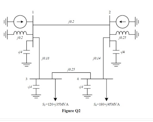
Transcribed Image Text:j0.2
j0.2
j0.25
-j4
j0.18
j0.14
j0.25
S3=120+/35MVA
S=180+/45MVA
Figure Q2
Transcribed Image Text:(b) Figure Q2 shows a power system network. The generators at Bus 1 and Bus 2
are represented by their equivalent current sources with the reactance in per unit
on a 100MVA base. The lines are represented by n model where the series and
shunt reactances are expressed in per unit on a 100MVA base as well. However,
the load located at Bus 3 and Bus 4 are expressed in MW and MVar.
Reconstruct the network impedance shown in the figure into the network
admittance by assuming the voltage magnitude at Bus 3 and Bus 4 are 1.0
per unit, respectively.
(i)
(11)
Calculate the bus admittance matrix of the system.
Expert Solution
This question has been solved!
Explore an expertly crafted, step-by-step solution for a thorough understanding of key concepts.

Step by step
Solved in 3 steps with 2 images

Knowledge Booster


Learn more about
Need a deep-dive on the concept behind this application? Look no further. Learn more about this topic, electrical-engineering and related others by exploring similar questions and additional content below.Recommended textbooks for you
Power System Analysis and Design (MindTap Course …
Electrical Engineering
ISBN:
9781305632134
Author:
J. Duncan Glover, Thomas Overbye, Mulukutla S. Sarma
Publisher:
Cengage Learning
Power System Analysis and Design (MindTap Course …
Electrical Engineering
ISBN:
9781305632134
Author:
J. Duncan Glover, Thomas Overbye, Mulukutla S. Sarma
Publisher:
Cengage Learning