Q 4(a) Consider the circuit shown in Figure 4. It includes a voltage source, e:(t), and a 6 volt battery. Find suitable state-variable equations for the system. Write an output equation for the output voltage eo. 2 H 6 V 1Ω F0.5 F Figure 4 Q 4(b)
Q 4(a) Consider the circuit shown in Figure 4. It includes a voltage source, e:(t), and a 6 volt battery. Find suitable state-variable equations for the system. Write an output equation for the output voltage eo. 2 H 6 V 1Ω F0.5 F Figure 4 Q 4(b)

Introductory Circuit Analysis (13th Edition)
13th Edition
ISBN:9780133923605
Author:Robert L. Boylestad
Publisher:Robert L. Boylestad
Chapter1: Introduction
Section: Chapter Questions
Problem 1P: Visit your local library (at school or home) and describe the extent to which it provides literature...

Related questions
Question
please ans a
Transcribed Image Text:omega
M(t)
0.02*u^3
1
0.2
1/10
XoS
omegadot->omega
1.
XoS
idot->i
4
R
e_R
![Q 4(a)
Consider the circuit shown in Figure 4. It includes a voltage source, e:(t), and a
6 volt battery. Find suitable state-variable equations for the system.
Write an output equation for the output voltage e..
2 H
6 V
1Ω
e(6)
0.5 F
Figure 4
Q 4(b)
The state-variable equation for a device with an electrical heater providing heat input
flux, q:(t), and which loses heat through both conduction and radiation, is
where the temperature of the device, 8, and the ambient temperature, 8,, are in
kelvin. The ambient temperature is 300 K. You will create a model of the system to
be used when designing a system to control e. When controlled, e will vary but will
have an average value of 1500 K.
1) If c = 1.0 x 10° J/K, R = 20.0 x 10⁻³ - K/I, and oA = 1.0 x 10-81/s/K*, find
the operating value of q:(t).
2) Find a linearized incremental state-variable equation for the system given
those parameters. Simplify it.
Q 4(c)
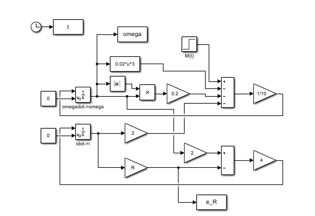
Consider the simplified wind turbine Simulink model shown in Figure 5.
1) Find the state-variable equations for the system. You don't need to specify
what the input function M(t) is. Also, find the output equation for eg. [5 marks]
2) The Simulink model is saved in a file named turbine". Write Matlab code to
run it three times, using a loop, with R = 100, R = 200 and R = 300. For each
run, your code should produce a separate chart containing two subplots: one
of w against t, and one of eg against t. There's no need to include code to
add titles or labels.](/v2/_next/image?url=https%3A%2F%2Fcontent.bartleby.com%2Fqna-images%2Fquestion%2F413ec67e-878b-460e-a505-37a914e65723%2Fdcb11f92-84c5-44d8-8b3a-88ec17e46258%2F6xketg9_processed.jpeg&w=3840&q=75)
Transcribed Image Text:Q 4(a)
Consider the circuit shown in Figure 4. It includes a voltage source, e:(t), and a
6 volt battery. Find suitable state-variable equations for the system.
Write an output equation for the output voltage e..
2 H
6 V
1Ω
e(6)
0.5 F
Figure 4
Q 4(b)
The state-variable equation for a device with an electrical heater providing heat input
flux, q:(t), and which loses heat through both conduction and radiation, is
where the temperature of the device, 8, and the ambient temperature, 8,, are in
kelvin. The ambient temperature is 300 K. You will create a model of the system to
be used when designing a system to control e. When controlled, e will vary but will
have an average value of 1500 K.
1) If c = 1.0 x 10° J/K, R = 20.0 x 10⁻³ - K/I, and oA = 1.0 x 10-81/s/K*, find
the operating value of q:(t).
2) Find a linearized incremental state-variable equation for the system given
those parameters. Simplify it.
Q 4(c)
Consider the simplified wind turbine Simulink model shown in Figure 5.
1) Find the state-variable equations for the system. You don't need to specify
what the input function M(t) is. Also, find the output equation for eg. [5 marks]
2) The Simulink model is saved in a file named turbine". Write Matlab code to
run it three times, using a loop, with R = 100, R = 200 and R = 300. For each
run, your code should produce a separate chart containing two subplots: one
of w against t, and one of eg against t. There's no need to include code to
add titles or labels.
Expert Solution
This question has been solved!
Explore an expertly crafted, step-by-step solution for a thorough understanding of key concepts.

Step by step
Solved in 2 steps with 2 images

Knowledge Booster


Learn more about
Need a deep-dive on the concept behind this application? Look no further. Learn more about this topic, electrical-engineering and related others by exploring similar questions and additional content below.Recommended textbooks for you
Introductory Circuit Analysis (13th Edition)
Electrical Engineering
ISBN:
9780133923605
Author:
Robert L. Boylestad
Publisher:
PEARSON

Delmar's Standard Textbook Of Electricity
Electrical Engineering
ISBN:
9781337900348
Author:
Stephen L. Herman
Publisher:
Cengage Learning

Programmable Logic Controllers
Electrical Engineering
ISBN:
9780073373843
Author:
Frank D. Petruzella
Publisher:
McGraw-Hill Education
Introductory Circuit Analysis (13th Edition)
Electrical Engineering
ISBN:
9780133923605
Author:
Robert L. Boylestad
Publisher:
PEARSON
Delmar's Standard Textbook Of Electricity
Electrical Engineering
ISBN:
9781337900348
Author:
Stephen L. Herman
Publisher:
Cengage Learning
Programmable Logic Controllers
Electrical Engineering
ISBN:
9780073373843
Author:
Frank D. Petruzella
Publisher:
McGraw-Hill Education

Fundamentals of Electric Circuits
Electrical Engineering
ISBN:
9780078028229
Author:
Charles K Alexander, Matthew Sadiku
Publisher:
McGraw-Hill Education

Electric Circuits. (11th Edition)
Electrical Engineering
ISBN:
9780134746968
Author:
James W. Nilsson, Susan Riedel
Publisher:
PEARSON

Engineering Electromagnetics
Electrical Engineering
ISBN:
9780078028151
Author:
Hayt, William H. (william Hart), Jr, BUCK, John A.
Publisher:
Mcgraw-hill Education,