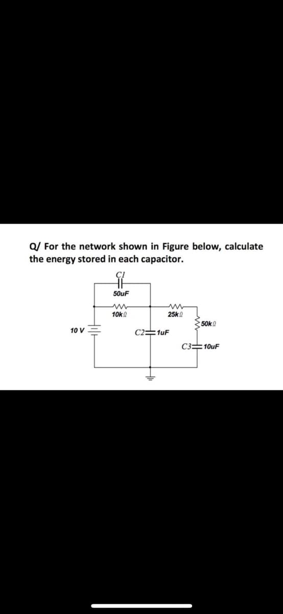
Q/ For the network shown in Figure below, calculate the energy stored in each capacitor. 50uF 10ka 25k 50k! 10 V C2=1uF C3=10uF


Q: 4. For the circuit shown in Figure...., determine (a) the total circuit capacitance, (b) the total…
A:
Q: For the circuit shown in the Figure Q2(a), calculate the voltage across each capacitor. C1 C2 30mF…
A:
Q: A 6-uF and a 10-uF capacitor is connected in parallel are in series with a 12-uF capacitor. The…
A:
Q: a) Find the equivalent capacitance and the total charge for the circuit in Figure 2. 0.001 uF C3 100…
A:
Q: C1 6 μF 4 μF C2 3 μF 12 μF FIGURE LINK .Determine the equivalent capacitance at terminals a-b of the…
A:
Q: 4) A circuit in Figure consists of paralel-plate capacitors with and without dielectrics. Dielectric…
A: A capacitor consists of two conducting plates separated by an insulator with some distance(d), which…
Q: 2) Solve the following values in the given figure 2.0. a) Total Capacitance, Ct. b) Total Charge,…
A: Let three capacitors C1 , C2 ,C3 are connected in series than equivalant capacitance is Ceq. (1/Ceq)…
Q: 4. Design and draw a self-commutation (with capacitor initially charged) circuit, where the time to…
A: Since you have asked multiple question, we will solve the first question for you. If you want any…
Q: The current in the circuit is known to bei=B1e−2000tcos1500t+B2e−2000tsin1500t, t≥0.The capacitor…
A: The current in the circuit is given as, The equation of natural current response in under damped is…
Q: 3. Four capacitors are connected to a EMF as shown with C, = 20 µF, C2 = 4 µF, C3 = 3 µF, and C4 = 4…
A:
Q: How large must inductor Lx be in order to provide a total inductance of 2.5 H in this network of…
A:
Q: (d) A capacitor of 100 microfarad is connected in series with a coil of resistance 5 ohm and…
A:
Q: Consider the circuit shown in the figure below, where C, = 8.00 µF, C, = 6.00 µF, and AV = 22.0 V.…
A:
Q: have to capacitors C1=400 F , C2=200 F connected in series and voltage applied by 120V. a- draw…
A: If c1 and C2 are in series Then equivalent capacitance is C1×C2C1+C2 Voltage across capacitor 1 is…
Q: In the circuit given below; A) Equivalent capacity, B) Total load, C) The load per capacitor, D) The…
A: Note: Since we only answer up to 3 sub-parts, we’ll answer the first 3. Please resubmit the question…
Q: A 12-Volt battery charges the four capacitors shown in Figure 5.12.1. C, Figure 5.12.1 Let C = 1 µF,…
A: If capacitors C1 and C2 are in series equivalent capacitor is C1×C2C1+C2 If capacitors C1 and C2 are…
Q: The inductor in the figure (Figure 1) has inductance 0.260 H and carries a current in the direction…
A: Given: Inductor having inductance, L = 0.260 H Current decreasing at uniform rate, didt=-1.80×10⁻²…
Q: Four different capacitors are hooked up to a battery as shown in the circuit diagram below. The…
A:
Q: C2 20 mF V1 С1 C3 С4 50 V 15 mF 25 mF 35 mF
A:
Q: Q/ For the network shown in Figure below, calculate the energy stored in each capacitor. HE 50uF…
A:
Q: 8 µF 6 µF 6 µF C3 µF C4 12 V C(uF) V (Volts) Energy (J) C2 C3 C4 CT
A: Energy cross different capacitor is found below: Energy across capacitor C1: C1=6μF,V=12VE1=C1V22…
Q: The figure shows a circuit that contains five identical resistors with resistance R = 10 ohms, one…
A:
Q: Homework 2 Find the voltage across each of the capacitors in the circuit shown below: 40 µF 60 µF H…
A: first calculate equivalent capacitance seen by the source and then find total charge from source.…
Q: V2 = c. The two capacitors shown above have been connected for some time and have reached their…
A:
Q: 200 pF 1200 pF 40 V 400 pF C4 : 600 pF Find the total capacitance for the circuit above. Just write…
A: Given data Capacitance is C1 = 1200 pF Capacitance is C2 = 200 pF Capacitance is C3 = 400 pF…
Q: The capacitors are arranged as shown in Figure below. C1 = 100 µF, C2 = 200 µF, C3 = 300 µF, C4 =…
A: Given: V=100V C1=100μFC2=200μFC3=300μFC4=400μFC5=500μFC6=600μF
Q: Q/ For the network shown in Figure below, calculate the energy stored in each capacitor. 50uF 10k!…
A: At steady-state in a DC circuit, no current flows through a capacitor, i.e. a capacitor acts as an…
Q: A. Simplify the circuit below by finding the equivalent resistance and equivalent capacitance. Show…
A: Given circuit shown
Q: (a) Figure 2 shows a circuit in a graphics tablet. At an instant, the values of the electronic…
A:
Q: A 30 V battery is used to charge four mica capacitors as shown in Figure Q2 (a). i. Determine the…
A: In the circuit, 4 mica based capacitor are connected as shown in the figure. Find the equivalent…
Q: C2 C3 60 V Figure 1: Circuit with four capacitors and a switch a) Figure 1 shows capacitors C1 =…
A: Since a and b are not interlinked question as per the guidelines of Bartleby we supposed to answer…
Q: A 2-nF capacitor with a 5-µC charge on it is discharged through a 2-k2 resistor. What is the maximum…
A: In this question , we will find maximum current in circuit with capacitor...
Q: Q3 The voltage across a 10 mF capacitor varies as shown in Figure Q3 (a). Determine and plot the…
A:
Q: A 12-Volt battery charges the four capacitors shown in Figure 5.12.1. C Figure 5.12.1 Let C = 1 µF,…
A: Given circuit is - Given that switch is open. Given values are - C1=1μFC2=2μFC3=3μFC4=4μF
Q: 1- In the figure below, the battery has a potential difference of 10.0 V and the five capacitors…
A:
Q: Q3/B/ For the circuit shown in the Figure below calculate the values of V2 and Vo at the initial…
A: In this question, Find the output voltage Vo and V2 as shown in the figure. First op amplifier is…
Q: An inductor of 2 henrys, a resistor of 16 ohms and a capacitor of 0.02 farads are connected in…
A:
Q: Section 3: Superposition with Inductors and Capacitors Given the following circuit: solve for…
A: First we will find out response due to both source then we will add them to find overall response .
Q: In the figure below, V =10 V, C, = C, = 4.0 µF , C, = 6.0 µF and C; = 2.0 µF . What is the charge on…
A:
Q: a. Find the equivalent capacitance. b. Find the voltage and charge on each C2 capacitor. C1 1 uF…
A:
Q: Q/ For the network shown in Figure below, calculate the energy stored in each capacitor. ÇI 50uF…
A:
Q: The voltage across a 10 mF capacitor varies as shown in Figure Q3 (a). Determine and plot the…
A:
Q: How much energy is stored in the electrical fields in the capacitors (in total) shown below? (b) Is…
A: It is given that: C1=3.0 μF=3×10⁻⁶ FC2=6.0 μF=6×10⁻⁶ FC3=3.0 μF=3×10⁻⁶ FC4=3.0 μF=3×10⁻⁶ FV=400 V
Q: A coil of resistance R and inductance L is connected in series with a 50 μF capacitor, figure If the…
A: Given data, I=3∠30°AC=50μFf=50Hz
Q: 5. Compute the individual values and the total values of the capacitance, charge and voltage of the…
A: To find the total capacitance , charge on each capacitor and voltage across each capacitor
Q: R1 Vs R2 +21 www R3 R4 ?For the circuit shown in the figure above, what is the value of the…
A: Brief description: In the above given question we need to calculate the value of capacitor voltage…
Q: A 30 V battery is used to charge four mica capacitors as shown in Figure Q2 (a). i. Determine the…
A:
Q: H.W: for the circuit shown in figure find: (a) the 12uF 4uF charge in each capacitor. (b) The energy…
A: In this question, We need to charge on each capacitance, energy on each capacitors? And also find…
Q: Note: Unit od capactors are mF, Unit of inductors are H. 3mf 34 Cap =? I Leq=? com
A:

Step by step
Solved in 2 steps with 1 images


- Three capacitors having capacitance values of 20F,40F, and 50F are connected in parallel to a 60 - Hz power line. An ammeter indicates a circuit current of 8.6 amperes. How much current is flowing through the 40F capacitor?You are a journeyman electrician working in an industrial plant. Your task is to connect an inductor to a 480-V, 60-Hz line. To determine the proper conductor and fuse size for this installation, you need to know the amount of current the inductor will draw from the line. The nameplate on the inductor indicates that it has an inductance of 0.1 H. An ohmmeter reveals that it has a wire resistance of 10 . How much current should this inductor draw when connected to the line?4. In what form is the energy of a capacitor stored?
- You are working in an industrial plant. You have been instructed to double the capacitance connected to a machine. The markings on the capacitor, however, are not visible. The capacitor is connected to 560 volts and an ammeter indicates a current of 6 amperes flowing to the capacitor. What size capacitor should be connected in parallel with the existing capacitor? What is the minimum AC voltage rating of the new capacitor? What is the minimum DC voltage rating of the new capacitor? What is the minimum KVAR size that can be used in this installation?A capacitor uses air as a dielectric and has a capacitance of 3 F. A dielectric material is inserted between the plates without changing the spacing, and the capacitance becomes 15 F. What is the dielectric constant of this material?You are an electrician working in an industrial plant. You discover that the problem with a certain machine is a defective capacitor. The capacitor is connected to a 240-volt AC circuit. The information on the capacitor reveals that it has a capacitance value of 10 mF and a voltage rating of 240 VAC. The only 10-mF AC capacitor in the storeroom is marked with a voltage rating of 350 WVDC. Can this capacitor be used to replace the defective capacitor? Explain your answer.
- You find that a 25-F capacitor connected to 480 VAC is defective. The storeroom has no capacitors with a 480-VAC rating. However, you find two capacitors rated at 50 F and 370 VAC. Can these two capacitors be connected in such a manner that they can replace the defective capacitor? If yes, explain how they are connected and why the capacitors will not be damaged by the lower voltage rating. If no, explain why they cannot be used without damaging the capacitor.The charges of the 2C, C, 2C capacitance capacitors in the figure are qk, qi and qm, respectively. Accordingly, what kind of relationship is there between qk, qi and qm?Having stabilized the fuel, you look to your computer for next steps. You are told that the spacecraft uses a "start capacitor" that must reach a required voltage in order to start its engine. This voltage is determined by the fixed capacitance and charge as a function of time, q(t) . These capacitors are charged and stored in your current location and must be brought to the spacecraft. Your computer provides you with the following definitions: Charge: The charge as a function of time is q(t)=∫i(t)dt , where i(t)=36t^5+15t^2−6 is the current as a function of time. You need to provide the computer with the function q(t) in order for it to appropriately charge the start capacitor. If an unknown constant is needed, it can be included using "+ C", being sure to use a capital letter as the lowercase is used for capacitance. q(t)=
- Refer to the diagram below. Compute the total capacitance, voltage and charge across each capacitor given that the total voltage is 120V. Please help, I've been getting ridiculously long decimal values and I don't know what to do.Capacitance= 4uF2) Determine the time constant of the circuit for the capacities 3) For the capacity value, calculate the estimated time to come to the final state.4) Plot capacitor current and voltage graphs and show if it works in harmony with the time constant you calculated. NOTE: if you want you can use falstad online circuit simulator.Determine the equivalent capacitance of each of the circuits in the figure shown. Note: I leave the image of the exercises in Spanish, but it is easy to understand. Also in the other image is the correct final answer, for checking.