The figure shows a circuit that contains five identical resistors with resistance R = 10 ohms, one inductors with inductance L = 4 mH, and an ideal battery with emf = 14V. What is the current I in Amp through the battery long after the switch is closed? R. Select one: Oa. 2.80A Ob. 0.40A Oc.9.80A Od. 4.90A Oe 245A
The figure shows a circuit that contains five identical resistors with resistance R = 10 ohms, one inductors with inductance L = 4 mH, and an ideal battery with emf = 14V. What is the current I in Amp through the battery long after the switch is closed? R. Select one: Oa. 2.80A Ob. 0.40A Oc.9.80A Od. 4.90A Oe 245A

Delmar's Standard Textbook Of Electricity
7th Edition
ISBN:9781337900348
Author:Stephen L. Herman
Publisher:Stephen L. Herman
Chapter17: Resistive-inductive Series Circuits
Section: Chapter Questions
Problem 2PA: You are a journeyman electrician working in an industrial plant. Your task is to connect an inductor...

Related questions
Question
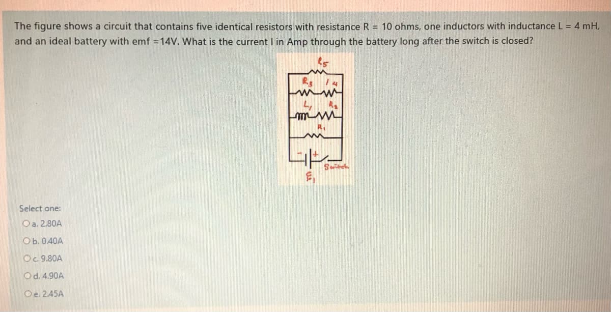
Transcribed Image Text:The figure shows a circuit that contains five identical resistors with resistance R = 10 ohms, one inductors with inductance L = 4 mH,
and an ideal battery with emf = 14V. What is the current I in Amp through the battery long after the switch is closed?
R 14
4,
mm M
Select one:
Oa. 2.80A
Ob. 0.40A
Oc. 9.80A
Od. 4.90A
Oe. 245A
Expert Solution
This question has been solved!
Explore an expertly crafted, step-by-step solution for a thorough understanding of key concepts.

This is a popular solution!

Trending now
This is a popular solution!

Step by step
Solved in 2 steps with 2 images

Knowledge Booster


Learn more about
Need a deep-dive on the concept behind this application? Look no further. Learn more about this topic, electrical-engineering and related others by exploring similar questions and additional content below.Recommended textbooks for you
Delmar's Standard Textbook Of Electricity
Electrical Engineering
ISBN:
9781337900348
Author:
Stephen L. Herman
Publisher:
Cengage Learning
Delmar's Standard Textbook Of Electricity
Electrical Engineering
ISBN:
9781337900348
Author:
Stephen L. Herman
Publisher:
Cengage Learning