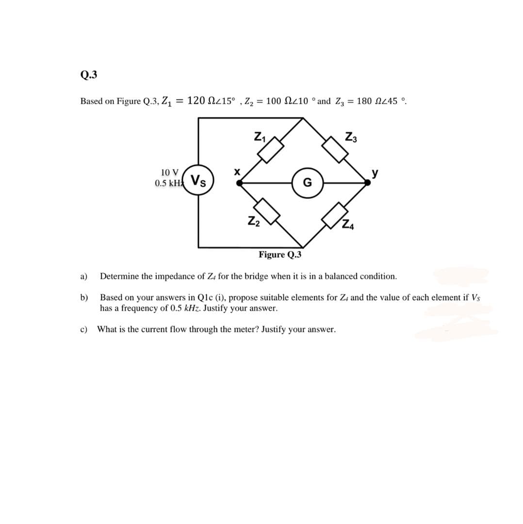
Q.3 Based on Figure Q.3, Z1 = 120 N215° , Z, = 100 N410 ° and Za = 180 NL45 °. Z3 10 V 0.5 kH Vs Z2 Figure Q.3 a) Determine the impedance of Z4 for the bridge when it is in a balanced condition. Based on your answers in Qlc (i), propose suitable elements for Z4 and the value of each element if Vs has a frequency of 0.5 kHz. Justify your answer. b) c) What is the current flow through the meter? Justify your answer.
Q: Consider the circuit diagram where Vs = 2300 Vrms Z₂ Z₁ Z₂ Find: 1. The apparent power delivered by…
A:
Q: Power System Analysis
A: The answer to your problem is given below.
Q: InclassofENG100youwereaskedtoconnectacoilofresistance50Ωand…
A:
Q: 3.5. Optimum Power Transfer What is the simple formula for the optimum complex load impedance Z, for…
A: Load resistor, when variable, allows variable current to flow. The maximum power is transferred when…
Q: The following impedances are connected in parallel in the electric circuit. Z, = 4 + 9j Z2 = 4 – 1…
A: We are authorized to answer 3 subparts at a time so i am answering only first 3 subparts please…
Q: Find current I, in the following circuit using the phasor approach, if Z1= 40 0, Zz= j30 0, Zg= 40…
A:
Q: The load impedance ZL in the circuit is adjusted until maximum average power is transferred to ZL.1.…
A: (1) The load impedance with reference to primary side (Z’L) of the transformer is: By applying…
Q: In PowerWorld Simulator Problem 2.32 (see Figure 2.28) a 8 MW/4 Mvar load is supplied at 13.8 kV…
A: There are multiple questions. Since you have not mentioned which part you are looking for, so we are…
Q: 3. A system consists of two plants connected by a tie and a load is located at plant two. When 100MW…
A:
Q: 4. (a) An a.c. voltage of v = 2+ v3j volts, is applied across an impedance of Z = 1- 2j ohms. ()…
A:
Q: Answer the following points in detail and rigorously. Instead of resorting to formulas, develop from…
A: Suppose you know P and Q for a two-terminal element. What is the power factor of this element? When…
Q: Plant-1 P2 Plant-2 Load In the above system shown, a transmission loss of 2.5 MW is incurred if 50…
A: Given:-λ=20IC1=0.01P1+12IC2=0.04P2+16Ploss=2.5MWP1=50MW From the…
Q: Ę Referring to Fig. 12.87, we have, 1,2+(₁+1)ZE 1₂2, +(1+1₂) ZE and Subtracti - 12000 √√3 Som eq.…
A: In the given questions we need to verify the given results by simply the step.
Q: Three branches having impedances of Z1, Z2, and Z3 0, respectively, are connected in parallel. TI…
A:
Q: The load impedance ZL for the circuit shown is adjusted until maximum average power is delivered to…
A: (A) The maximum average power to the load ZL, when ZL is adjustable is: Where, The magnitude of the…
Q: 6. Fill in the following table U.S Power System Standards Fill in the table for a correctly wired…
A: U.S National Electric code for voltage and frequency would be 208 V (Line-Line ), 60Hz…
Q: A 3-ph, 50 Hz, 150 km length O.H.T.L. supplies a load with P MW load at 0.80 lag P.f. and 110 kV…
A: Note: We are authorized to answer three sub parts at a time, since you have not mentioned which part…
Q: 2. In the simple system below, draw the V-Q curve for the load bus if P-D0. What is the maximum…
A: As per the guidelines given, We can only provide the solution of the first question in multiple type…
Q: 1 4/0° V -j4 2 6Ω 8 Ω j5 Ω el 10/0° V 3/0° 14 13
A:
Q: Which network theorem states "The current through, or voltage across, an element in a linear…
A: According To superposition theorem, it state that "The current through, or voltage across, an…
Q: In the circuit below Z1 = 40/-60° and Z2 60/40° 2. Calculate: a) The currents I1, l2 and Is b) The…
A: Note: As per guidelines will be solving only the first 3 subparts. Please repost for others…
Q: Consider the following AC circuit: R1 R R2 Aj sin(wt) C2 Az sin(wt + 45°) reference a) Use nodal…
A: Given circuit shown
Q: L2 500 mH R1 100 N ww C2 25 µF R2 v,(t) (A 50 Hz L1 800 mH 200 N C1 12 µF
A:
Q: or the following SLD, take SB = 100 MVA and VB = 250 kV at the load bus to he impedance diagram.…
A: In the question we have given all the per unit values on their respective bases. But since base…
Q: Compose the mesh equations. 10 Q j10 O j10 Q ... ll ell ä) 10 V [1] sine :-j10 2 [12] sine @mesh 1:…
A: In this question, We need to determine the value of impedance Z parameters ?
Q: An unbalanced, 3-phase, 4-wire, Y-connected load is connected to a 6900 V Y system (the line-line…
A:
Q: The following impedances are connected in parallel in the electric circuit. Z, = 4+ 9j Z2 = 4 – 1 Z3…
A: DeMoive's theorem formula is (cosx±jsinx) m=cosmx±jsinmx
Q: (a) Calculate the input impedance of the infinite ladder network shown in the figure below. (Z =…
A: (a) Since, the given circuit is of the infinite length and the total impedance of the circuit will…
Q: Question 1 Using Nodal Analysis, what is the value of Vg if the reference node is at node f if Z₁ =…
A:
Q: 22040'V 5012 V₁ ZI 7+j8r 220x00V 50112 21√32 24 15 tj sr 8+140/23 V2 67132 zzt Z₂ 72040 Sorta 26 It…
A: Maxwell's mesh method :
Q: ion 13 Find the bus impedance matrix for the system whose reactance diagram is showm in below fig A…
A: We have to find the impedance matrix from the given diagram,On forming the Z bus matrix we have…
Q: As shown in Figure Q1, a 50 Hz AC source, denoted as Vs, is connected to loads having the following…
A:
Q: 1. For the circuit shown in Figure 1, let f= 60 Hz, vs(t) = 590 cos(2r60t + 30°) R1 = 15 N, R2 = 22…
A:
Q: A 300 m ring distributor has loads as shown in Fig. 13.45 where distances are in metres. The resis-…
A:
Q: Show that the impedance seen looking into the terminals a,b in thecircuit is given by the…
A: The auto-transformer circuit is shown below: The impedance observed from the terminals ab is…
Q: Consider the circuit diagram below. Using mesh analysis, compute the currents (a) IR1, (b) Iz1, and…
A:
Q: Need help with D and E only, thank you
A:
Q: Question 1 A 208-V three-phase power system is shown in Figure Q4.1. It consists of an ideal 208- V…
A: In the 3 phase balance power system Find the apparent power ,active power and reactive power across…
Q: VBR VRY VYB Figure Q1 (a) Q1 (a) Calculate the percent voltage unbalance for the phasor form in…
A: symmetrical components is analysis power in unbalanced system . symmetrical components is used in…
Q: Compose the mesh equations. 10 Q j10 O j10 O l i5 v sine 10 V [11] [12] :-10 O sine @mesh 1: Z111 +…
A:
Q: Question one A balanced star connected load comprises of 20 ohm resistance and 0.07 Henry inductance…
A: Given that Rph=20 ohmLph=0.07 Hf=50 HzVL=415V Calculate the indctive reactance…
Q: Q.23: For the following electric circuit, find Z and Y (1200+j850)2 (1500+j900)2 parameters? Also,…
A:
Q: In the network, find the value of ZL for maximum power transfer. The load impedance has both…
A: Given: Consider the following network: The load impedance has both variable resistance and variable…
Q: Compose the mesh equations. 10 Q j10 Q ... j10 Q ll ll ) 10 V [1] sine j5 V sine [12] -j10 0 @mesh…
A: The solution is given below
Q: Q3: Consider the Y-A three-phase circuit in Fig. 1 with: Three-phase circuits Van = 50 cos(100t +…
A:
Q: If I have a circuit like that shown in the figure below, we can replace the resistor and inductor…
A: Given
Q: TUTORIAL PROBLEMS A 300 m ring distributor has loads as shown in Fig. 13.45 where distances are in…
A: we are supposed to answer one question at a time,so that i answer for first question only.
Q: Please show all work and calculations in detail. Thank you!
A: As per Bartleby policy we can answer only one part at a time, I am answering part a repost it for…
Q: 21 Vi: 12ov Lo° Vt= 1 (ov Lo VsE 90 V Lo° 73: 3-J 8A 24= 8t jizn 25: 9t J4A
A:
Q: Figure is at sinusoidal steady state.The sources are given as: v1(t) = A1 cos(ω1t) v2(t) = A2…
A: Hello. Since you have posted multiple questions and not specified which question needs to be solved,…
Step by step
Solved in 2 steps with 1 images
- Consider the load convention that is used for the RLC elements shown in Figure 2.2 of the text. A. If one says that an inductor absorbs zero real power and positive reactive power. is it (a) True (b) False B. If one says that a capacitor absorbs zero real power and negative reactive power (or delivers positive reactive power), is it (a) False (b) True C. If one says that a (positive-valued) resistor absorbs (positive) real power and zero reactive power, is it (a) True (b) FalseFind the following: the power drawn by the 100ohm variable resistor If the variable resistor is set to 200-ohms, instead of 100-ohms, What is the power drawn by the 200-ohms resistor? total current of the system Is the circuit inductive, capacitive, or neither (resistive)? NOTE: Polar form for Voltage & Current. Rectangular form for ImpedanceSolve the impedances of the circuit using mesh analysis. Complete the table given. Note: If there are no coefficients for a particular parameter, input zero. Round off only the final answer to five decimal places if possible. @mesh 1: Z11I1 + Z12I2 +Z13I3 + Z14I4 = Source1 @mesh 2: Z21I1 + Z22I2 + Z23I3 + Z24I4 = Source2 @mesh 3: Z31I1 + Z32I2 + Z33I3 + Z34I4 = Source3 @mesh 4: Z41I1 + Z42I2 + Z43I3 + Z44I4 = Source4
- Let a series RLC network be connected to a source voltage V, drawing a current I. (a) In terms of the load impedance Z = Z angleZ, find expressions for P and Q, from complex power considerations.(b) Express p(t) in terms of P and Q, by choosing i(t)= sqrt2*I* cos wt.(c) For the case of Z = R + jwL + 1 /jwC, interpret the result of part (b) in terms of P, QL, and QC. In particular, if w^2*LC=1, when the inductive and capacitive reactances cancel, comment on what happens.If the values of real power and reactive power is specified for a bus, then it is called as PQ bus. Select one: True FalseFind the total impedance, voltage drop on the 100-ohm resistor, draw the phasor diagram of the voltage and current at R1, total power (apparent) delivered by the current source, draw the phasor diagram of the voltage and current at the source. Also, is the circuit inductive, capacitive, or neither (resistive)? please give the step-by-step solution NOTE: Polar form for Voltage & Current. Rectangular form for Impedance
- In the network, find the value of ZL for maximum power transfer. The load impedance has both variable resistance and variable reactance. In addition, calculate the maximum power dissipated under these conditions, PS: Show complete/step-by-step solution without rounding off any numbers.The currents in each branch of a two - branched parallel circuit are given by expression i1 = 7.07sin(314t - π/4) A and i2 = 21.2sin((314t - π/3) A. The supply voltage is given by the expression v = 354sin 314t V. Determine the impedance Z1 and Z2. a. Z1 = 50.07 Ω, Z2 = 16.7 Ω b. Z1 = 35.4 Ω, Z2 = 8.35 Ω c. Z1 = 10.0 Ω, Z2 = 10.2 Ω d. Z1 = 14.46 Ω, Z2 = 14.14 ΩI have just started my first Semester (Fall 2021) out of 4 semesters in Master of Applied Science (M.A.S) in Power Engineering at Illinois Institute of Technology. I did not clearly undersand the course enrollment system because I am new to the system, so I ended up enrolling in courses; ECE58-Microgrid Design and Operation, and ECE579-Computer Aided Design of Electrical Machines. It appears ECE582 listed ECE418 (Power System Analysis) as a prerequisite; and ECE539 requires ECE319 (Fundamentals of Power Engineering) and ECE412(Hybrid Electric Vehicle Drives) as prerequisites. Let me hasten to add that I graduated in 2009 in a different academic setup in Africa in Electrical Engineering. So, not only do I have to cover the gap of about 12 year out of classroom, but I have compounded the problem by jumping into advanced courses before enrolling into foundation courses. Unfortunately I can no longer switch courses as the enrollment window has passed. I am only left with one option; to…
- Consider the microgrid of Figure 3.66. A three-phase transformer, T1, israted at 500 kVA, 220 VY grounded/440 V delta, a transformerwith a reactance of 3.5%.Themicrogridis supplied from anAC bus of a PV generating station.The DC bus rated at 540 V.The distributionlineis 10mileslong and has a series impedance of 0.1 + j1.0 Ω per mile and local load of 100 kVA at 440 V. The microgrid is connected to the local power grid using a three-phase transformer T2, rated at 440 V Y grounded/13.2 kV delta,500 kVA with a reactance of 8%. Compute the per unitimpedance diagram of the microgrid system. Assume the voltage base of 13.2 kV on the local power grid side and kVA base of 500InclassofENG100youwereaskedtoconnectacoilofresistance50Ωand inductance0.318Hwithacircuitcomprisinga75Ωresistorinserieswitha 159µFcapacitor.Andyouconnectedyourresultingcircuittoa240v,50HzAC supply. Calculate: (a)the supply current of your circuit; EV(7) (b)the circuit impedance, resistance and reactance; CR(7) (c)the phase angle of the resulting current,use (sine) as your reference and explain your result. AN(6) Question21.1 We have two loads in delta and another in star in parallel, the impedances of the branches of the delta are equal and we have that RΔ=1p.u. and XΔ=0.75 p.u., while in the star we have equal values of the branches, but formed by admittances where we have the conductance in parallel GY=0.64 p.u. and inductive susceptance of BY=-j0.48 p.u. If the loads are being supplied by a positive sequence balanced three-phase source with line-to-line voltage of phases a and b of Vab=1∠ 30º, if the base values are line-to-line base voltage of 1kV and three-phase base power of 100kW. DetermineA) Line and phase voltages, line and phase currents of the load in delta, line and phase voltages of the star, line and phase currents of the star.B) Obtain separately the phasor diagram of the delta and star load with the values obtained in A), indicate on the scale that these are 1 p.u.=5cm for example.C) obtain the power triangle and the power factor separately for each load. D) Obtain the power…