Q1) A A 200-KVA, 480-V, 50-Hz, Y-connected synchronous generator with a rated field current of 5 A was tested, and the following data were taken: I. Voc at the rated If was measured to be 540 V. Isc at the rated If was found to be 300 A. II. When a dc voltage of 10 V was applied to two of the terminals, a current of 25 A was measured. 1) Find the values of the armature resistance and the approximate synchronous reactance in ohms that would be used in the generator model at the rated conditions. 2) Sketch the full equivalent circuit of synchronous generator. 3) Sketch phasor diagrams for a synchronous generator (lagging.leading). 4) Explain convenient way to compare the voltage behavior of two generators ? III.
Q1) A A 200-KVA, 480-V, 50-Hz, Y-connected synchronous generator with a rated field current of 5 A was tested, and the following data were taken: I. Voc at the rated If was measured to be 540 V. Isc at the rated If was found to be 300 A. II. When a dc voltage of 10 V was applied to two of the terminals, a current of 25 A was measured. 1) Find the values of the armature resistance and the approximate synchronous reactance in ohms that would be used in the generator model at the rated conditions. 2) Sketch the full equivalent circuit of synchronous generator. 3) Sketch phasor diagrams for a synchronous generator (lagging.leading). 4) Explain convenient way to compare the voltage behavior of two generators ? III.

Introductory Circuit Analysis (13th Edition)
13th Edition
ISBN:9780133923605
Author:Robert L. Boylestad
Publisher:Robert L. Boylestad
Chapter1: Introduction
Section: Chapter Questions
Problem 1P: Visit your local library (at school or home) and describe the extent to which it provides literature...

Related questions
Question
i need the answer quickly
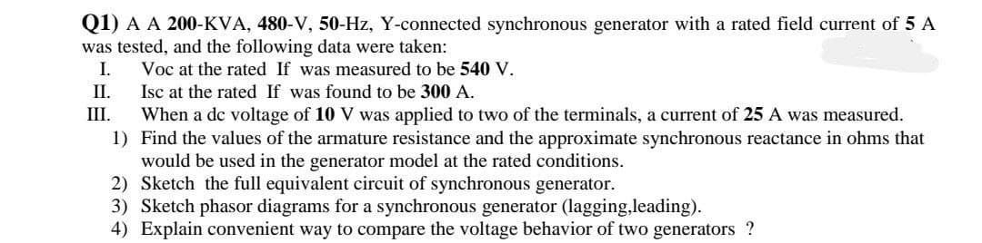
Transcribed Image Text:Q1) A A 200-KVA, 480-V, 50-Hz, Y-connected synchronous generator with a rated field current of 5 A
was tested, and the following data were taken:
I.
Voc at the rated If was measured to be 540 V.
II.
Isc at the rated If was found to be 300 A.
III.
When a de voltage of 10 V was applied to two of the terminals, a current of 25 A was measured.
1) Find the values of the armature resistance and the approximate synchronous reactance in ohms that
would be used in the generator model at the rated conditions.
2) Sketch the full equivalent circuit of synchronous generator.
3) Sketch phasor diagrams for a synchronous generator (lagging,leading).
4) Explain convenient way to compare the voltage behavior of two generators ?
Expert Solution
This question has been solved!
Explore an expertly crafted, step-by-step solution for a thorough understanding of key concepts.

Step by step
Solved in 4 steps with 4 images

Knowledge Booster


Learn more about
Need a deep-dive on the concept behind this application? Look no further. Learn more about this topic, electrical-engineering and related others by exploring similar questions and additional content below.Recommended textbooks for you
Introductory Circuit Analysis (13th Edition)
Electrical Engineering
ISBN:
9780133923605
Author:
Robert L. Boylestad
Publisher:
PEARSON

Delmar's Standard Textbook Of Electricity
Electrical Engineering
ISBN:
9781337900348
Author:
Stephen L. Herman
Publisher:
Cengage Learning

Programmable Logic Controllers
Electrical Engineering
ISBN:
9780073373843
Author:
Frank D. Petruzella
Publisher:
McGraw-Hill Education
Introductory Circuit Analysis (13th Edition)
Electrical Engineering
ISBN:
9780133923605
Author:
Robert L. Boylestad
Publisher:
PEARSON
Delmar's Standard Textbook Of Electricity
Electrical Engineering
ISBN:
9781337900348
Author:
Stephen L. Herman
Publisher:
Cengage Learning
Programmable Logic Controllers
Electrical Engineering
ISBN:
9780073373843
Author:
Frank D. Petruzella
Publisher:
McGraw-Hill Education

Fundamentals of Electric Circuits
Electrical Engineering
ISBN:
9780078028229
Author:
Charles K Alexander, Matthew Sadiku
Publisher:
McGraw-Hill Education

Electric Circuits. (11th Edition)
Electrical Engineering
ISBN:
9780134746968
Author:
James W. Nilsson, Susan Riedel
Publisher:
PEARSON

Engineering Electromagnetics
Electrical Engineering
ISBN:
9780078028151
Author:
Hayt, William H. (william Hart), Jr, BUCK, John A.
Publisher:
Mcgraw-hill Education,