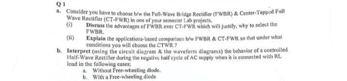
Q1 a. Consider you have to choose b/w the Full-Wave Bridge Rectifier (FWBR) & Center-Tapped Full Wave Rectifier (CT-FWR) in one of your semester Lab projects. (1) Discuss the advantages of FWBR over CT-FWR which will justify, why to select the FWBR. (11) Explain the applications-based comparison b/w FWBR & CT-FWR so that under what conditions you will choose the CTWR.? b. Interpret (using the circuit diagram & the waveform diagrams) the behavior of a controlled Half-Wave Rectifier during the negative half cycle of AC supply when it is connected with RL load in the following cases; a. Without Free-wheeling diode. b. With a Free-wheeling diode
Q1 a. Consider you have to choose b/w the Full-Wave Bridge Rectifier (FWBR) & Center-Tapped Full Wave Rectifier (CT-FWR) in one of your semester Lab projects. (1) Discuss the advantages of FWBR over CT-FWR which will justify, why to select the FWBR. (11) Explain the applications-based comparison b/w FWBR & CT-FWR so that under what conditions you will choose the CTWR.? b. Interpret (using the circuit diagram & the waveform diagrams) the behavior of a controlled Half-Wave Rectifier during the negative half cycle of AC supply when it is connected with RL load in the following cases; a. Without Free-wheeling diode. b. With a Free-wheeling diode

Power System Analysis and Design (MindTap Course List)
6th Edition
ISBN:9781305632134
Author:J. Duncan Glover, Thomas Overbye, Mulukutla S. Sarma
Publisher:J. Duncan Glover, Thomas Overbye, Mulukutla S. Sarma
Chapter4: Transmission Line Parameters
Section: Chapter Questions
Problem 4.2P: The temperature dependence of resistance is also quantified by the relation R2=R1[ 1+(T2T1) ] where...

Related questions
Question
(Q1 ,b) Required
Explain the applications-based comparison b/w FWBR & CT-FWR so that under what conditions you will choose the CTWR.? b. Interpret (using the circuit diagram & the waveform diagrams) the behavior of a controlled Half-Wave Rectifier during the negative half cycle of AC supply when it is connected with RL
load in the following cases; a. Without Free-wheeling diode.
Transcribed Image Text:Q1
a. Consider you have to choose b/w the Full-Wave Bridge Rectifier (FWBR) & Center-Tapped Full
Wave Rectifier (CT-FWR) in one of your semester Lab projects.
(i)
Discuss the advantages of FWBR over CT-FWR which will justify, why to select the
FWBR.
Explain the applications based comparison b/w FWBR & CT-FWR so that under what
conditions you will choose the CTWR.?
b. Interpret (using the circuit diagram & the waveform diagrams) the behavior of a controlled
Half-Wave Rectifier during the negative half cycle of AC supply when it is connected with RL
load in the following cases;
a. Without Free-wheeling diode.
b. With a Free-wheeling diode
Expert Solution
This question has been solved!
Explore an expertly crafted, step-by-step solution for a thorough understanding of key concepts.
Step 1: Given information about the question.
VIEWStep 2: Discussing the advantages of FWBR over CT-FWR.
VIEWStep 3: Discussing the Applications based comparison,
VIEWStep 4: Explaining the conditions for choosing CT-FWR
VIEWStep 5: Explaining the behavior of the rectifier during the negative half cycle of AC supply without FWD.
VIEWStep 6: Explaining the behavior of the rectifier during the negative half cycle of AC supply with FWD.
VIEWSolution
VIEW
Step by step
Solved in 7 steps with 25 images

Knowledge Booster


Learn more about
Need a deep-dive on the concept behind this application? Look no further. Learn more about this topic, electrical-engineering and related others by exploring similar questions and additional content below.Recommended textbooks for you
Power System Analysis and Design (MindTap Course …
Electrical Engineering
ISBN:
9781305632134
Author:
J. Duncan Glover, Thomas Overbye, Mulukutla S. Sarma
Publisher:
Cengage Learning
Power System Analysis and Design (MindTap Course …
Electrical Engineering
ISBN:
9781305632134
Author:
J. Duncan Glover, Thomas Overbye, Mulukutla S. Sarma
Publisher:
Cengage Learning